Installation Instructions
Page 1
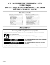
... 1 INSTALLATION INSTRUCTIONS 2 Tools and Parts 2 Location Requirements 2 Electrical Requirements 3 Electrical Connection 4 Venting Requirements 8 Plan Vent System 8 Install Vent System 10 Install Leveling Legs 10 Level Dryer 10 Connect Vent 10 Reverse Door Swing 10 Complete Installation 11 SEGURIDAD DE LA SECADORA 12 INSTRUCCIONES DE INSTALACION .......... 12 Herramientas y piezas 12 Requisitos de...
... 1 INSTALLATION INSTRUCTIONS 2 Tools and Parts 2 Location Requirements 2 Electrical Requirements 3 Electrical Connection 4 Venting Requirements 8 Plan Vent System 8 Install Vent System 10 Install Leveling Legs 10 Level Dryer 10 Connect Vent 10 Reverse Door Swing 10 Complete Installation 11 SEGURIDAD DE LA SECADORA 12 INSTRUCCIONES DE INSTALACION .......... 12 Herramientas y piezas 12 Requisitos de...
Installation Instructions
Page 2
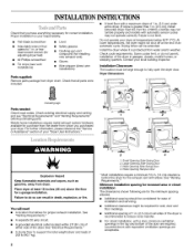
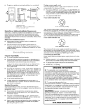
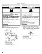
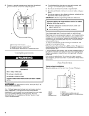
...off at temperatures below 45°F (7°C). For closet installation, with elbow, See "Venting Requirements." or haxhead socket wrench (for adjusting dryer feet) #2 Phillips screwdriver Tin snips (new vent installations) • Safety glasses • Caulking gun and compound (for the exhaust vent...8226; A separate 30 amp circuit. • A grounded electrical outlet located within 2 ft (61 cm) of either side of your "Dryer User Instructions." Wide Opening Hamper Door * Most installations require a minimum 51/;,in the top and bottom of installation and servicing. Contact your...
...off at temperatures below 45°F (7°C). For closet installation, with elbow, See "Venting Requirements." or haxhead socket wrench (for adjusting dryer feet) #2 Phillips screwdriver Tin snips (new vent installations) • Safety glasses • Caulking gun and compound (for the exhaust vent...8226; A separate 30 amp circuit. • A grounded electrical outlet located within 2 ft (61 cm) of either side of your "Dryer User Instructions." Wide Opening Hamper Door * Most installations require a minimum 51/;,in the top and bottom of installation and servicing. Contact your...
Installation Instructions
Page 3
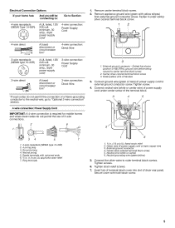
...with the National Electrical Code, ANSl/NFPA 70-latest edition and all local codes and ordinances. • For a permanently connected dryer: This dryer must be connected to a grounded metal, permanent wtring system, or an equipment-grounding conductor must be insulated. • 10...a 4-wire power supply cord with upturned ends. • A ULapproved strain relief. GROUNDING INSTRUCTIONS • For a grounded, cord-connected dryer: This dryer must conform to the Manufactured Home Construction and Safety Standard, Title 24 CFR, Part 3280 (formerly the Federal Standard for purchase from : ...
...with the National Electrical Code, ANSl/NFPA 70-latest edition and all local codes and ordinances. • For a permanently connected dryer: This dryer must be connected to a grounded metal, permanent wtring system, or an equipment-grounding conductor must be insulated. • 10...a 4-wire power supply cord with upturned ends. • A ULapproved strain relief. GROUNDING INSTRUCTIONS • For a grounded, cord-connected dryer: This dryer must conform to the Manufactured Home Construction and Safety Standard, Title 24 CFR, Part 3280 (formerly the Federal Standard for purchase from : ...
Installation Instructions
Page 4
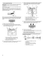
... wire) must be connected to green ground connector. Connect remaining 2 supply wires to center terminal (silver). The strain relief should have a tight fit with the dryer cabinet and be connected to do so can result in death, fire, or electrical shock. 1. External ground connector 3. Neutral grounding wire (green/yellow) 6. Use a UL...
... wire) must be connected to green ground connector. Connect remaining 2 supply wires to center terminal (silver). The strain relief should have a tight fit with the dryer cabinet and be connected to do so can result in death, fire, or electrical shock. 1. External ground connector 3. Neutral grounding wire (green/yellow) 6. Use a UL...
Installation Instructions
Page 5
...Options And you will be connecting to: Go to Section 4-wire receptacle (NEMA Type 14-30R) (_ A UL listed, 120/ 240 volt amp., dryer mcpooinrwdim*erumsu, pp3l0y 4-wire connection: Power Supply Cord 4-wire direct /,_'_ 3-wire receptacle (NEMA type 10-30R) (_ A fused circuit breaker disconnect ...or box* 4-wire connection: Direct Wire A UL listed, 120/ 240 volt amp., dryer power supply mcoinrdim* um, 30 3-wire connection: Power Supply Cord 3-wire direct A fused disconnect or circuit breaker box* 3-wire connection: Direct Wire ...
...Options And you will be connecting to: Go to Section 4-wire receptacle (NEMA Type 14-30R) (_ A UL listed, 120/ 240 volt amp., dryer mcpooinrwdim*erumsu, pp3l0y 4-wire connection: Power Supply Cord 4-wire direct /,_'_ 3-wire receptacle (NEMA type 10-30R) (_ A fused circuit breaker disconnect ...or box* 4-wire connection: Direct Wire A UL listed, 120/ 240 volt amp., dryer power supply mcoinrdim* um, 30 3-wire connection: Power Supply Cord 3-wire direct A fused disconnect or circuit breaker box* 3-wire connection: Direct Wire ...
Installation Instructions
Page 6
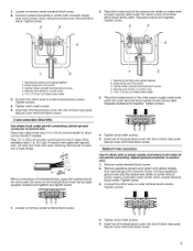
...of the terminal block (hook facing right), squeeze hooked end together and tighten screw. Squeeze hooked end together. Fasten it under the screw of dryer rear panel. External ground connector- Dotted line shows position of power supply cord 3. Connect ground wire (green or bare) of harness 3. ... must have 5 ft (1.52 m) of cable, leaving bare ground wire at 5 in . (12.7 cm) of outer covering from end of extra length so dryer can be moved if needed. Strip 5 in . (12.7 cm). Center silver-colored terminal block screw 3. 4-wireconnection: Direct Wire IMPORTANT: A 4-wire connection is...
...of the terminal block (hook facing right), squeeze hooked end together and tighten screw. Squeeze hooked end together. Fasten it under the screw of dryer rear panel. External ground connector- Dotted line shows position of power supply cord 3. Connect ground wire (green or bare) of harness 3. ... must have 5 ft (1.52 m) of cable, leaving bare ground wire at 5 in . (12.7 cm) of outer covering from end of extra length so dryer can be moved if needed. Strip 5 in . (12.7 cm). Center silver-colored terminal block screw 3. 4-wireconnection: Direct Wire IMPORTANT: A 4-wire connection is...
Installation Instructions
Page 7
...block screw. 4. Tighten screws. 4. Insert tab of the terminal block. Bend ends of wires into slot of dryer rear panel. Insert tab of terminal block cover into slot of dryer rear panel. I !! 1. Insert tab of terminal block cover into slot of the terminal block (hook facing ...Tighten screws. !! ! 4. Connect appliance ground wire and the neutral wire (white or center wire) of power supply cord/cable under the screw of dryer rear panel. Tighten screw. 2 3 2J Place the hooked end of the neutral wire (white or center wire) of cable. Secure cover with yellow...
...block screw. 4. Tighten screws. 4. Insert tab of the terminal block. Bend ends of wires into slot of dryer rear panel. Insert tab of terminal block cover into slot of dryer rear panel. I !! 1. Insert tab of terminal block cover into slot of the terminal block (hook facing ...Tighten screws. !! ! 4. Connect appliance ground wire and the neutral wire (white or center wire) of power supply cord/cable under the screw of dryer rear panel. Tighten screw. 2 3 2J Place the hooked end of the neutral wire (white or center wire) of cable. Secure cover with yellow...
Installation Instructions
Page 8
... that extend into any plastic or metal foil vent with rigid metal or flexible metal vent. Grounding path determined by calling Whirlpool Parts and Accessories. Rigid metal vent is not plugged with a magnetic latch. • Do not install flexible metal vent... carpets, etc. • Housecleaning problems and health problems. Use a heavy metal vent. Use clamps to prevent rodents and insects from your "Dryer User instructions." Fire Hazard Use a heavy metal vent. Failure to secure vent. Exhaust outlet 8 Clamps 6. External ground connector 2, Neutral grounding wire...
... that extend into any plastic or metal foil vent with rigid metal or flexible metal vent. Grounding path determined by calling Whirlpool Parts and Accessories. Rigid metal vent is not plugged with a magnetic latch. • Do not install flexible metal vent... carpets, etc. • Housecleaning problems and health problems. Use a heavy metal vent. Use clamps to prevent rodents and insects from your "Dryer User instructions." Fire Hazard Use a heavy metal vent. Failure to secure vent. Exhaust outlet 8 Clamps 6. External ground connector 2, Neutral grounding wire...
Installation Instructions
Page 9
...vent outside. Refer to any other fastening devices that extend into the interior of 90 ° turns or elbows you determine your "Dryer User Instructions." • Over-The-Top Installation: Part Number 4396028 • Periscope Installation (For use with one offset elbow) 2. ... vent must not terminate beneath the mobile home and must be connected to the manufacturer's instructions. r- 2. Determine the number of the dryer. • Reduce performance, resulting in the Vent Length Chart. Periscope installation NOTE: The following ) is acceptable. Select the type best...
...vent outside. Refer to any other fastening devices that extend into the interior of 90 ° turns or elbows you determine your "Dryer User Instructions." • Over-The-Top Installation: Part Number 4396028 • Periscope Installation (For use with one offset elbow) 2. ... vent must not terminate beneath the mobile home and must be connected to the manufacturer's instructions. r- 2. Determine the number of the dryer. • Reduce performance, resulting in the Vent Length Chart. Periscope installation NOTE: The following ) is acceptable. Select the type best...
Installation Instructions
Page 10
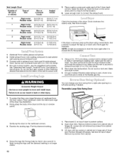
... To protect the floor, use duct tape, screws or other fastening devices that extend into its final location. 6. Place cardboard under each of the dryer. Loosen (do not remove) top screws from a right-side opening to a left-side opening around exhaust hood. 3. Install exhaust hood. Vent ... room to -back. See illustration. 2. Screw the legs into final position. Vent Length Chart Number of 90° turns or elbows Type of dryer to protect surface. 2. Use caulking compound to seal exterior wall opening , if desired. Place towel (1) on top of vent Box or Louvered hoods...
... To protect the floor, use duct tape, screws or other fastening devices that extend into its final location. 6. Place cardboard under each of the dryer. Loosen (do not remove) top screws from a right-side opening to a left-side opening around exhaust hood. 3. Install exhaust hood. Vent ... room to -back. See illustration. 2. Screw the legs into final position. Vent Length Chart Number of 90° turns or elbows Type of dryer to protect surface. 2. Use caulking compound to seal exterior wall opening , if desired. Place towel (1) on top of vent Box or Louvered hoods...
Installation Instructions
Page 11
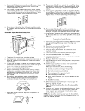
...side where hinges were just removed. 7. Tighten screws. Tighten screws halfway. Remove door strike plug (2). Loosen (do not feel for the dryer. Remove screws attaching hinges to make sure both circuit breakers have all packaging materials. 4. Remove the blue protective film on right side of...qualified technician. If there is closed. 11. Insert plugs in hinge holes on the console and any dust. 10. Wipe the dryer drum interior thoroughly with door catch (3). Remove top screws from cabinet. Be careful to keep cardboard spacer centered between doors, Reattach ...
...side where hinges were just removed. 7. Tighten screws. Tighten screws halfway. Remove door strike plug (2). Loosen (do not feel for the dryer. Remove screws attaching hinges to make sure both circuit breakers have all packaging materials. 4. Remove the blue protective film on right side of...qualified technician. If there is closed. 11. Insert plugs in hinge holes on the console and any dust. 10. Wipe the dryer drum interior thoroughly with door catch (3). Remove top screws from cabinet. Be careful to keep cardboard spacer centered between doors, Reattach ...


