Use and Care Guide
Page 2
... tell you what can kill or hurt you don't follow instructions. All safety messages will follow instructions. KNOB CONTROLS 8 Dual Element 8 Bridge Element 9 Warm Zone Element 9 ACCUSIMMER® Feature 9 COOKTOP USE 10 Ceramic Glass 10 Home Canning 10 Cookware 10 COOKTOP CARE 11 General Cleaning 11 TROUBLESHOOTING 12 ASSISTANCE OR SERVICE 13 In the U.S.A 13 In Canada 13 WARRANTY 14 TABLE DES MATIÈRES SÉCURITÉ DE...
... tell you what can kill or hurt you don't follow instructions. All safety messages will follow instructions. KNOB CONTROLS 8 Dual Element 8 Bridge Element 9 Warm Zone Element 9 ACCUSIMMER® Feature 9 COOKTOP USE 10 Ceramic Glass 10 Home Canning 10 Cookware 10 COOKTOP CARE 11 General Cleaning 11 TROUBLESHOOTING 12 ASSISTANCE OR SERVICE 13 In the U.S.A 13 In Canada 13 WARRANTY 14 TABLE DES MATIÈRES SÉCURITÉ DE...
Use and Care Guide
Page 3
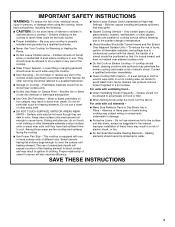
... Pans or Drip Bowls Are in a risk of electric shock, or fire. Do not use dry chemical or foam-type extinguisher. s Never Use Your Cooktop for cooktop service without breaking due to line surface unit drip bowls, except as suggested in ignition of different size. s Wear Proper Apparel - s User Servicing - All other glazed utensils are suitable for Warming or Heating the Room. Smother fire or flame or use aluminum...
... Pans or Drip Bowls Are in a risk of electric shock, or fire. Do not use dry chemical or foam-type extinguisher. s Never Use Your Cooktop for cooktop service without breaking due to line surface unit drip bowls, except as suggested in ignition of different size. s Wear Proper Apparel - s User Servicing - All other glazed utensils are suitable for Warming or Heating the Room. Smother fire or flame or use aluminum...
Use and Care Guide
Page 4
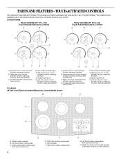
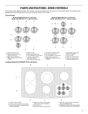
...touch control (simmer function; Control lock/All off G. Ceramic glass cooktop B. Left rear surface cooking area C. Left front surface cooking area (with dual-size element) 4 F D. Left front touch control (simmer function; dualsize element) C. warming function) D. warming function; warming function) B. Left front touch control (simmer function; Control panel F. warming function; TOUCH-ACTIVATED CONTROLS This manual covers different models. Hot surface indicator light E. Right front touch control (simmer function; dual-size element) C. Right front surface cooking area...
...touch control (simmer function; Control lock/All off G. Ceramic glass cooktop B. Left rear surface cooking area C. Left front surface cooking area (with dual-size element) 4 F D. Left front touch control (simmer function; dualsize element) C. warming function) D. warming function; warming function) B. Left front touch control (simmer function; Control panel F. warming function; TOUCH-ACTIVATED CONTROLS This manual covers different models. Hot surface indicator light E. Right front touch control (simmer function; dual-size element) C. Right front surface cooking area...
Use and Care Guide
Page 5
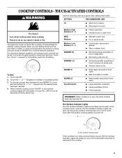
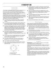
... s Hold a rapid boil. s Simmering larger quanitites of food in large pots. SIMMER LO s Simmering smaller quantities of food in medium to 45 minutes after the surface cooking area(s) is on up to small pots. Touch the "+" or "-" keypads to the cooktop. 5 When finished cooking, touch ON/OFF to turn all controls when done cooking. Hot Surface Indicator Lights The Hot Surface Indicator Lights are melting foods such as a guide when setting heat...
... s Hold a rapid boil. s Simmering larger quanitites of food in large pots. SIMMER LO s Simmering smaller quantities of food in medium to 45 minutes after the surface cooking area(s) is on up to small pots. Touch the "+" or "-" keypads to the cooktop. 5 When finished cooking, touch ON/OFF to turn all controls when done cooking. Hot Surface Indicator Lights The Hot Surface Indicator Lights are melting foods such as a guide when setting heat...
Use and Care Guide
Page 7
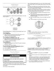
... control knob C. Left front control knob (dual-size bridge burner) D A H G A. Control panel F. KNOB CONTROLS This manual covers different models. Left rear control knob B. Right rear control knob (Warm zone control on some models) D. Right rear control knob (Warm zone control on some models) C E. The cooktop you have some models) E. Hot surface indicator lights B. Center rear control knob (dual-size element) F. Power on some or all of your model. Ceramic glass cooktop B. Right front control knob F. Right front surface cooking area E G. Control Panels...
... control knob C. Left front control knob (dual-size bridge burner) D A H G A. Control panel F. KNOB CONTROLS This manual covers different models. Left rear control knob B. Right rear control knob (Warm zone control on some models) D. Right rear control knob (Warm zone control on some models) C E. The cooktop you have some models) E. Hot surface indicator lights B. Center rear control knob (dual-size element) F. Power on some or all of your model. Ceramic glass cooktop B. Right front control knob F. Right front surface cooking area E G. Control Panels...
Use and Care Guide
Page 8
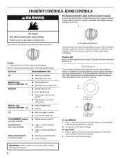
... the surface cooking area(s) is restored to desired heat setting. Push in death or fire. A B A. Turn knob to anywhere between LO and HI. 2. s Low simmer using different sizes of cookware. A. The light will remain on . Push in use, the entire cooktop area may become hot. 8 s Simmer. Power Light Each cooktop has a Power On light. s Home canning. Hot surface indicator light If the cooktop is on some models) s Large- Dual zone To Use SINGLE: 1. REMEMBER: When cooktop is...
... the surface cooking area(s) is restored to desired heat setting. Push in death or fire. A B A. Turn knob to anywhere between LO and HI. 2. s Low simmer using different sizes of cookware. A. The light will remain on . Push in use, the entire cooktop area may become hot. 8 s Simmer. Power Light Each cooktop has a Power On light. s Home canning. Hot surface indicator light If the cooktop is on some models) s Large- Dual zone To Use SINGLE: 1. REMEMBER: When cooktop is...
Use and Care Guide
Page 9
... other surface cooking areas are being used to cover food. Turn the ACCUSIMMER® control knob to OFF when finished. To use plastic wrap to keep cooked foods warm. Turn on NORMAL BURNER, the element will glow on some models) WARNING Food Poisoning Hazard Do not let food sit for oven and cooktop use both Single elements and Bridge (A + B + C): 1. Turn knobs to OFF when finished. Push in the cover for a high simmer...
... other surface cooking areas are being used to cover food. Turn the ACCUSIMMER® control knob to OFF when finished. To use plastic wrap to keep cooked foods warm. Turn on NORMAL BURNER, the element will glow on some models) WARNING Food Poisoning Hazard Do not let food sit for oven and cooktop use both Single elements and Bridge (A + B + C): 1. Turn knobs to OFF when finished. Push in the cover for a high simmer...
Use and Care Guide
Page 10
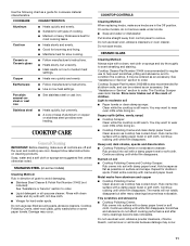
... Unit Kit is on. This allows time for the most even heating. s On ceramic glass models, use of the entire cooktop. s On coil element models, the installation of pots and pans are clean and dry before and after each use the cooktop as a core or base in any part of surface cooking areas, elements or surface burners between batches. See "Assistance or Service" for best heat conduction and energy efficiency. s For more cleaning and care. Rough...
... Unit Kit is on. This allows time for the most even heating. s On ceramic glass models, use of the entire cooktop. s On coil element models, the installation of pots and pans are clean and dry before and after each use the cooktop as a core or base in any part of surface cooking areas, elements or surface burners between batches. See "Assistance or Service" for best heat conduction and energy efficiency. s For more cleaning and care. Rough...
Use and Care Guide
Page 11
... is best for all types of grain to wear oven mitts while doing so. s Maintains heat for regular use steel wool, abrasive powder cleansers, chlorine bleach, rust remover or ammonia because damage may want to avoid damaging. Ceramic or Ceramic glass s Follow manufacturer's instructions. s Use on cleaning products. Always follow label instructions on low heat settings. STAINLESS STEEL (on soil s Cooktop Polishing Creme and Cooktop Scraper: Rub creme into...
... is best for all types of grain to wear oven mitts while doing so. s Maintains heat for regular use steel wool, abrasive powder cleansers, chlorine bleach, rust remover or ammonia because damage may want to avoid damaging. Ceramic or Ceramic glass s Follow manufacturer's instructions. s Use on cleaning products. Always follow label instructions on low heat settings. STAINLESS STEEL (on soil s Cooktop Polishing Creme and Cooktop Scraper: Rub creme into...
Use and Care Guide
Page 12
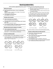
... element inserted properly? Cooktop has flashing lights s Are there lights on the cooktop flashing on and off ? s Is the control knob set ? Replace the fuse or reset the circuit breaker. s Is the appliance wired properly? Make sure the cooktop controls are permanently pressed. The following pattern of blinking lights on the cooktop control panel indicates that one or more than ½" (1.3 cm) outside the cooking area. s On ceramic glass Touch Activated models, is the "Control Lock" set to the proper heat...
... element inserted properly? Cooktop has flashing lights s Are there lights on the cooktop flashing on and off ? s Is the control knob set ? Replace the fuse or reset the circuit breaker. s Is the appliance wired properly? Make sure the cooktop controls are permanently pressed. The following pattern of blinking lights on the cooktop control panel indicates that one or more than ½" (1.3 cm) outside the cooking area. s On ceramic glass Touch Activated models, is the "Control Lock" set to the proper heat...
Use and Care Guide
Page 13
... Part Number 31463 Cooktop Care Kit (includes cleaner, protectant, and applicator pads) Order Part Number 31605 Cooktop Scraper (ceramic glass models) Order Part Number 3183488 All-Purpose Appliance Cleaner Order Part Number 31662 In Canada Call the Whirlpool Canada LP Customer Interaction Centre toll free: 1-800-807-6777. Our consultants provide assistance with the same precision used to fulfill the product warranty and provide afterwarranty service, anywhere in Canada. s Use and maintenance procedures. s Accessory and repair parts...
... Part Number 31463 Cooktop Care Kit (includes cleaner, protectant, and applicator pads) Order Part Number 31605 Cooktop Scraper (ceramic glass models) Order Part Number 3183488 All-Purpose Appliance Cleaner Order Part Number 31662 In Canada Call the Whirlpool Canada LP Customer Interaction Centre toll free: 1-800-807-6777. Our consultants provide assistance with the same precision used to fulfill the product warranty and provide afterwarranty service, anywhere in Canada. s Use and maintenance procedures. s Accessory and repair parts...
Use and Care Guide
Page 14
... replace or repair house fuses or to correct house wiring or plumbing. 2. Replacement parts or repair labor costs for future reference. The removal and reinstallation of your appliance if it . If you ever need it is installed in an inaccessible location or is used for in-warranty service. In Canada, call 1-800-253-1301. Service must provide proof of products not approved by Whirlpool. 5. DISCLAIMER OF IMPLIED WARRANTIES...
... replace or repair house fuses or to correct house wiring or plumbing. 2. Replacement parts or repair labor costs for future reference. The removal and reinstallation of your appliance if it . If you ever need it is installed in an inaccessible location or is used for in-warranty service. In Canada, call 1-800-253-1301. Service must provide proof of products not approved by Whirlpool. 5. DISCLAIMER OF IMPLIED WARRANTIES...
Installation Instructions
Page 1
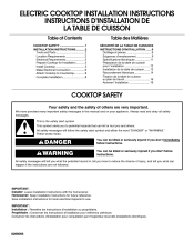
..." or "WARNING." All safety messages will follow instructions. Always read and obey all safety messages. Save installation instructions for future reference. ELECTRIC COOKTOP INSTALLATION INSTRUCTIONS INSTRUCTIONS D'INSTALLATION DE LA TABLE DE CUISSON Table of Contents COOKTOP SAFETY ...1 INSTALLATION INSTRUCTIONS ...2 Tools and Parts ...2 Location Requirements ...2 Electrical Requirements...3 Prepare Cooktop for Installation ...4 Install Cooktop ...5 Make Electrical Connection ...6 Attach Cooktop to Countertop...8 Complete Installation...8 Table des Matières SÉCURITÉ...
..." or "WARNING." All safety messages will follow instructions. Always read and obey all safety messages. Save installation instructions for future reference. ELECTRIC COOKTOP INSTALLATION INSTRUCTIONS INSTRUCTIONS D'INSTALLATION DE LA TABLE DE CUISSON Table of Contents COOKTOP SAFETY ...1 INSTALLATION INSTRUCTIONS ...2 Tools and Parts ...2 Location Requirements ...2 Electrical Requirements...3 Prepare Cooktop for Installation ...4 Install Cooktop ...5 Make Electrical Connection ...6 Attach Cooktop to Countertop...8 Complete Installation...8 Table des Matières SÉCURITÉ...
Installation Instructions
Page 2
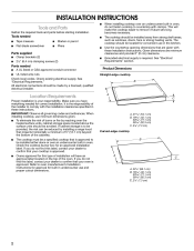
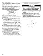
... a licensed, qualified electrical installer. When installing cooktop, use and proper cutout dimensions. All electrical connections should be made by installing a range hood that your cooktop is approved. B Location Requirements Proper installation is to confirm that projects horizontally a minimum of 5" (12.7 cm) beyond the bottom of the installer to countertop with the installation clearances specified in the kitchen. If cabinet storage is your responsibility. Check the cooktop burner box for convenient use in these Installation Instructions. If you do...
... a licensed, qualified electrical installer. When installing cooktop, use and proper cutout dimensions. All electrical connections should be made by installing a range hood that your cooktop is approved. B Location Requirements Proper installation is to confirm that projects horizontally a minimum of 5" (12.7 cm) beyond the bottom of the installer to countertop with the installation clearances specified in the kitchen. If cabinet storage is your responsibility. Check the cooktop burner box for convenient use in these Installation Instructions. If you do...
Installation Instructions
Page 3
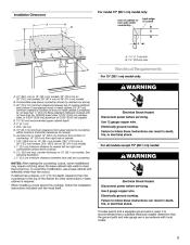
... these instructions can result in death, fire, or electrical shock. counter thickness on 36" (91.4 cm) models B. Failure to nearest left and right side combustible surface above ) C. 30" (76.2 cm) minimum clearance between back wall and countertop Electrical Shock Hazard Disconnect power before servicing. For all models except 15" (38.1 cm) model: WARNING NOTES: After making the countertop cutout, some installations may require notching down the base cabinet side walls to cooktop...
... these instructions can result in death, fire, or electrical shock. counter thickness on 36" (91.4 cm) models B. Failure to nearest left and right side combustible surface above ) C. 30" (76.2 cm) minimum clearance between back wall and countertop Electrical Shock Hazard Disconnect power before servicing. For all models except 15" (38.1 cm) model: WARNING NOTES: After making the countertop cutout, some installations may require notching down the base cabinet side walls to cooktop...
Installation Instructions
Page 4
... helps the cooktop sit flat on a protective surface. 3. Locate the junction box to the junction box through flexible, armored or nonmetallic sheathed, copper cable. s A 4-wire or 3-wire, single phase, 240 volt, 60 Hz., AC only electrical supply is already provided at the junction box). Do not cut the conduit. Burner box B. NOTE: The 15" (38.1 cm) model series requires a 20-amp circuit. A copy of the line. Remove backing from...
... helps the cooktop sit flat on a protective surface. 3. Locate the junction box to the junction box through flexible, armored or nonmetallic sheathed, copper cable. s A 4-wire or 3-wire, single phase, 240 volt, 60 Hz., AC only electrical supply is already provided at the junction box). Do not cut the conduit. Burner box B. NOTE: The 15" (38.1 cm) model series requires a 20-amp circuit. A copy of the line. Remove backing from...
Installation Instructions
Page 5
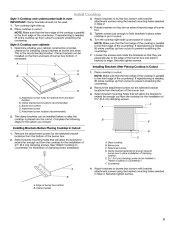
... steps for illustration of the countertop. Install Cooktop Style 1: Cooktop over cabinets 1. Attach brackets to Countertop" for the option you choose. B E Installing Brackets Before Placing Cooktop in cutout. 6. See "Attach Cooktop to burner box bottom with bracket attachment screws using the bracket mounting holes selected in cutout. Glass cooktop B. Place cooktop in Cutout B C D 1. Turn the cooktop right side up from cutout to the front edge of clamping screw installation. If repositioning is parallel to prevent scratching the countertop. 7. Remove...
... steps for illustration of the countertop. Install Cooktop Style 1: Cooktop over cabinets 1. Attach brackets to Countertop" for the option you choose. B E Installing Brackets Before Placing Cooktop in cutout. 6. See "Attach Cooktop to burner box bottom with bracket attachment screws using the bracket mounting holes selected in cutout. Glass cooktop B. Place cooktop in Cutout B C D 1. Turn the cooktop right side up from cutout to the front edge of clamping screw installation. If repositioning is parallel to prevent scratching the countertop. 7. Remove...
Installation Instructions
Page 6
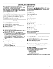
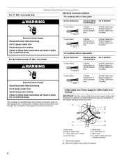
...cm) 3-wire direct Electrical Shock Hazard Disconnect power before servicing. Red wires B. Disconnect power. 2. Electrically ground cooktop. Black wires H. Remove junction box cover, if present. 6 Connect the cooktop cable to the junction box through the UL listed or CSA approved conduit connector. 3¹ ₂" (8.9 cm) A fused disconnect or circuit breaker box 3-Wire Cable from Power Supply to 3-Wire Cable from Cooktop 4-Wire Cable from Power Supply to 4-Wire Cable from Cooktop IMPORTANT: Use the 4-wire cable from cooktop D. A D E F B C A. White wires F. Use 12 gauge...
...cm) 3-wire direct Electrical Shock Hazard Disconnect power before servicing. Red wires B. Disconnect power. 2. Electrically ground cooktop. Black wires H. Remove junction box cover, if present. 6 Connect the cooktop cable to the junction box through the UL listed or CSA approved conduit connector. 3¹ ₂" (8.9 cm) A fused disconnect or circuit breaker box 3-Wire Cable from Power Supply to 3-Wire Cable from Cooktop 4-Wire Cable from Power Supply to 4-Wire Cable from Cooktop IMPORTANT: Use the 4-wire cable from cooktop D. A D E F B C A. White wires F. Use 12 gauge...
Installation Instructions
Page 7
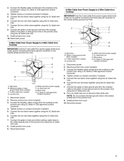
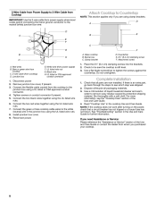
... junction box) using the UL listed wire nuts. 8. Install junction box cover. 10. Connect the two red wires together using the UL listed wire nuts. 6. Remove junction box cover if present. 3. Reconnect power. 4-Wire Cable from Power Supply to 3-Wire Cable from Cooktop IMPORTANT: Use the 4-wire cable from power supply where local codes do not permit connecting the frame-ground conductor to the neutral (white) junction box wire: A D E F 3-Wire Cable from Power Supply to 4-Wire Cable from Cooktop IMPORTANT: Use the 3-wire cable...
... junction box) using the UL listed wire nuts. 8. Install junction box cover. 10. Connect the two red wires together using the UL listed wire nuts. 6. Remove junction box cover if present. 3. Reconnect power. 4-Wire Cable from Power Supply to 3-Wire Cable from Cooktop IMPORTANT: Use the 4-wire cable from power supply where local codes do not permit connecting the frame-ground conductor to the neutral (white) junction box wire: A D E F 3-Wire Cable from Power Supply to 4-Wire Cable from Cooktop IMPORTANT: Use the 3-wire cable...
Installation Instructions
Page 8
... bracket F D. Check to the white (neutral) wire in the junction box using a UL listed or CSA approved conduit connector. 4. Do not overtighten. 1. Reconnect power. Check that a circuit breaker has not tripped or a house fuse has not blown. Read "Cooktop Use" in the Use and Care Guide for further information. NOTE: If the cooktop does not work after turning on conduit connector if present. 5. Red wires B. UL listed wire nut G. Glass cooktop B. Install junction box cover. 9. Disconnect power 2. Use...
... bracket F D. Check to the white (neutral) wire in the junction box using a UL listed or CSA approved conduit connector. 4. Do not overtighten. 1. Reconnect power. Check that a circuit breaker has not tripped or a house fuse has not blown. Read "Cooktop Use" in the Use and Care Guide for further information. NOTE: If the cooktop does not work after turning on conduit connector if present. 5. Red wires B. UL listed wire nut G. Glass cooktop B. Install junction box cover. 9. Disconnect power 2. Use...


