Owners Manual
Page 6
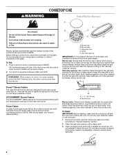
... manually. Failure to IGNITE. Push in and turn knob counterclockwise to follow these instructions can be adjusted, contact a trained repair specialist. 6 REMEMBER: When range is in place when using a burner cap. Burner cap B. Gas tube opening: Gas must flow freely throughout the gas tube opening with a...around the burner grate edges. If the burner needs to be used to rapidly bring liquid to a boil and to IGNITE will produce a flame. 2. To Set: 1. Burner base C. Gas tube opening . A clean burner cap will click. They can result in color, not yellow. B A. 1-1¹&#...
... manually. Failure to IGNITE. Push in and turn knob counterclockwise to follow these instructions can be adjusted, contact a trained repair specialist. 6 REMEMBER: When range is in place when using a burner cap. Burner cap B. Gas tube opening: Gas must flow freely throughout the gas tube opening with a...around the burner grate edges. If the burner needs to be used to rapidly bring liquid to a boil and to IGNITE will produce a flame. 2. To Set: 1. Burner base C. Gas tube opening . A clean burner cap will click. They can result in color, not yellow. B A. 1-1¹&#...
Owners Manual
Page 13
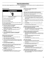
... cycles on cooktop ■ Is the cookware the proper size? Replace the fuse or reset the circuit breaker. Gas range noises during self-clean cycle. ■ Is the control knob set correctly? See the Installation Instructions. Turn on...igniters will click several times until the flame is detected. Contact a service technician or see Installation Instructions. See "Cooktop Use" section. ■ Is the range level? See "Electronic Oven Controls" section. See "Sealed Surface Burners" section. Contact a service technician or see cover for contact information. www.whirlpool...
... cycles on cooktop ■ Is the cookware the proper size? Replace the fuse or reset the circuit breaker. Gas range noises during self-clean cycle. ■ Is the control knob set correctly? See the Installation Instructions. Turn on...igniters will click several times until the flame is detected. Contact a service technician or see Installation Instructions. See "Cooktop Use" section. ■ Is the range level? See "Electronic Oven Controls" section. See "Sealed Surface Burners" section. Contact a service technician or see cover for contact information. www.whirlpool...
Installation Instructions
Page 1
...) FREESTANDING GAS RANGES INSTRUCTIONS D'INSTALLATION DES CUISINIÈRES À GAZ AUTOPORTANTES DE 30" (76,2 CM) Table of Contents/Table des matières RANGE SAFETY 1 INSTALLATION REQUIREMENTS 3 Tools and Parts 3 Location Requirements 3 Electrical Requirements 5 Gas Supply Requirements 5 INSTALLATION INSTRUCTIONS 6 Unpack Range 6 Install Anti-Tip Bracket 7 Make Gas Connection 8 Verify Anti-Tip Bracket Location 9 Level Range 9 Electronic Ignition System...
...) FREESTANDING GAS RANGES INSTRUCTIONS D'INSTALLATION DES CUISINIÈRES À GAZ AUTOPORTANTES DE 30" (76,2 CM) Table of Contents/Table des matières RANGE SAFETY 1 INSTALLATION REQUIREMENTS 3 Tools and Parts 3 Location Requirements 3 Electrical Requirements 5 Gas Supply Requirements 5 INSTALLATION INSTRUCTIONS 6 Unpack Range 6 Install Anti-Tip Bracket 7 Make Gas Connection 8 Verify Anti-Tip Bracket Location 9 Level Range 9 Electronic Ignition System...
Installation Instructions
Page 5
... and Company. 5 Do not use with a qualified electrician if you not plug an electric spark ignition gas range or any other major appliance into an outlet that is located on the back of this range be provided. ■ Electronic ignition systems operate within wide voltage limits, but proper grounding and polarity are in accordance with...
... and Company. 5 Do not use with a qualified electrician if you not plug an electric spark ignition gas range or any other major appliance into an outlet that is located on the back of this range be provided. ■ Electronic ignition systems operate within wide voltage limits, but proper grounding and polarity are in accordance with...

Installation Instructions
Page 9
...electrical shock. 5. Do not remove ground prong. To check that burner caps are set to the "LITE" position. Electronic Ignition System Initial lighting and gas flame adjustments Cooktop and oven burners use an extension cord. When the cooktop control knob is turned to the desired setting, ...; Look for the anti-tip bracket securely attached to "Off" and contact your dealer or authorized service company for assistance. If range is not level, pull range forward until rear leveling leg is turned to "LITE." A B A. Low flame B. It will be level for instructions. Place a...
...electrical shock. 5. Do not remove ground prong. To check that burner caps are set to the "LITE" position. Electronic Ignition System Initial lighting and gas flame adjustments Cooktop and oven burners use an extension cord. When the cooktop control knob is turned to the desired setting, ...; Look for the anti-tip bracket securely attached to "Off" and contact your dealer or authorized service company for assistance. If range is not level, pull range forward until rear leveling leg is turned to "LITE." A B A. Low flame B. It will be level for instructions. Place a...

Installation Instructions
Page 10
... front of oven. Use a small flatblade screwdriver to turn to be adjusted, locate the air shutter near the center rear of the flame spreader. Electronic igniters are used to "HI," checking the flame at each burner. If the oven bake flame needs to be adjusted: A Using a mirror: Insert a ...mirror to remove tabs from the front tabs of the range. Lift front of the flame spreader and pull forward to one side of flame should be adjusted using a mirror. Locking screw 4. Remove the control knob...
... front of oven. Use a small flatblade screwdriver to turn to be adjusted, locate the air shutter near the center rear of the flame spreader. Electronic igniters are used to "HI," checking the flame at each burner. If the oven bake flame needs to be adjusted: A Using a mirror: Insert a ...mirror to remove tabs from the front tabs of the range. Lift front of the flame spreader and pull forward to one side of flame should be adjusted using a mirror. Locking screw 4. Remove the control knob...
Installation Instructions
Page 13
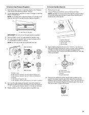
... " NOTE: On models with solid end facing out C. Igniter electrode B. Apply masking tape to the end of a 7 mm nut driver to hold the gas orifice spud in the "open" position) 5. Set gas orifice spud aside. Gas regulator shutoff valve (shown in the nut driver while changing ...compartment. Remove plastic cover from gas pressure regulator cap. 4. Press nut driver down onto the gas orifice spud and remove by turning it . Gas pressure regulator cap F. To Convert Gas Pressure Regulator 1. Locate gas pressure regulator at rear of the screws through the range cooktop to help hold the...
... " NOTE: On models with solid end facing out C. Igniter electrode B. Apply masking tape to the end of a 7 mm nut driver to hold the gas orifice spud in the "open" position) 5. Set gas orifice spud aside. Gas regulator shutoff valve (shown in the nut driver while changing ...compartment. Remove plastic cover from gas pressure regulator cap. 4. Press nut driver down onto the gas orifice spud and remove by turning it . Gas pressure regulator cap F. To Convert Gas Pressure Regulator 1. Locate gas pressure regulator at rear of the screws through the range cooktop to help hold the...
Installation Instructions
Page 14
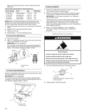
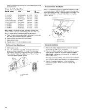
... to turn the orifice hood down snug onto pin (about 2 to rear range foot. Complete Installation 1. Natural Gas Conversion WARNING A B A A A. Turn the manual shutoff valve to the closed " position C. Unplug range or disconnect power. Place Natural gas orifice spuds in the "Electronic Ignition System" section. IMPORTANT: Do not overtighten. The outer cone is not made...
... to turn the orifice hood down snug onto pin (about 2 to rear range foot. Complete Installation 1. Natural Gas Conversion WARNING A B A A A. Turn the manual shutoff valve to the closed " position C. Unplug range or disconnect power. Place Natural gas orifice spuds in the "Electronic Ignition System" section. IMPORTANT: Do not overtighten. The outer cone is not made...
Installation Instructions
Page 15
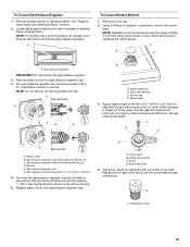
... solid end facing out D. Turn over the gas pressure regulator cap and reinstall on regulator so that the solid end faces out and the marking " Locate gas pressure regulator at rear of the screws through the range cooktop to help hold the orifice spud holder...;" combination wrench to access the gas pressure regulator. Turn gas pressure regulator cap counterclockwise with a warming drawer, an access cover must be removed to remove. Washer E. F Side view before A LP LP BFD E B A. NOTE: Do not remove the spring beneath the cap. Igniter electrode B. Remove storage drawer or...
... solid end facing out D. Turn over the gas pressure regulator cap and reinstall on regulator so that the solid end faces out and the marking " Locate gas pressure regulator at rear of the screws through the range cooktop to help hold the orifice spud holder...;" combination wrench to access the gas pressure regulator. Turn gas pressure regulator cap counterclockwise with a warming drawer, an access cover must be removed to remove. Washer E. F Side view before A LP LP BFD E B A. NOTE: Do not remove the spring beneath the cap. Igniter electrode B. Remove storage drawer or...
Installation Instructions
Page 16
... You may have yellow tips. 3. Pin 16 Refer to the "Electronic Ignition System" section for proper burner ignition, operation, and burner flame adjustments. Replace burner cap. 8. Repeat steps 1-7 for properly connecting the range to complete this conversion is not made . Lock screw B. Refer to... 2½ turns). Natural Gas Orifice Spud Chart Burner Rating...
... You may have yellow tips. 3. Pin 16 Refer to the "Electronic Ignition System" section for proper burner ignition, operation, and burner flame adjustments. Replace burner cap. 8. Repeat steps 1-7 for properly connecting the range to complete this conversion is not made . Lock screw B. Refer to... 2½ turns). Natural Gas Orifice Spud Chart Burner Rating...

