
Installation Instructions
Page 2
... in a prominent location, instructions for the customer's use gasoline or other appliance. it is the safety alert symbol. You can be killed or seriously injured if you don't follow instructions. TABLEOF CONTENTS DRYER SAFETY 2 iNSTALLATiON REQUIREMENTS 4 Location Requirements 4 Tools and Parts 4 Ebctricat Requirements 6 Gas Supply Requirements 7 Venting Requirements 8 INSTALLATION INSTRUCTIONS = GAS DRYER 10 Move Dryer into Position 10 Make Gas Connection 10 Connect Vent 10 Complete InstaUation 10 INSTALLATION INSTRUCTIONS = ELECTRIC DRYER ........ 11 Move...
... in a prominent location, instructions for the customer's use gasoline or other appliance. it is the safety alert symbol. You can be killed or seriously injured if you don't follow instructions. TABLEOF CONTENTS DRYER SAFETY 2 iNSTALLATiON REQUIREMENTS 4 Location Requirements 4 Tools and Parts 4 Ebctricat Requirements 6 Gas Supply Requirements 7 Venting Requirements 8 INSTALLATION INSTRUCTIONS = GAS DRYER 10 Move Dryer into Position 10 Make Gas Connection 10 Connect Vent 10 Complete InstaUation 10 INSTALLATION INSTRUCTIONS = ELECTRIC DRYER ........ 11 Move...
Installation Instructions
Page 3
... published user-repair instructions that could cause a load to dry articles containing foam rubber or similarly textured rubber-like materials. Close supervision of this Use and Care Guide or in the dryer. m Do not instal! m Clean lint screen before using a ball vaIve, it will be exposed to eliminate static unless recommended by the manufacturer of the dryer and exhaust vent should be cleaned periodica!ly by a qualified installer, service agency...
... published user-repair instructions that could cause a load to dry articles containing foam rubber or similarly textured rubber-like materials. Close supervision of this Use and Care Guide or in the dryer. m Do not instal! m Clean lint screen before using a ball vaIve, it will be exposed to eliminate static unless recommended by the manufacturer of the dryer and exhaust vent should be cleaned periodica!ly by a qualified installer, service agency...

Installation Instructions
Page 4
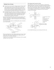
... materials and vapors, such as the dryer. The dryer must not be installed in a recessed area or closet. Read and follow the instructions provided with equivalent air openings are free of obstructions to water and/or weather. See "Recessed Area and Closet Installation Instructions" below for installing new exhaust vent) Pliers Putty knife Parts supplied Remove parts bag from dryer. Tools needed m 8" or 10" pipe wrench 8" or 10...
... materials and vapors, such as the dryer. The dryer must not be installed in a recessed area or closet. Read and follow the instructions provided with equivalent air openings are free of obstructions to water and/or weather. See "Recessed Area and Closet Installation Instructions" below for installing new exhaust vent) Pliers Putty knife Parts supplied Remove parts bag from dryer. Tools needed m 8" or 10" pipe wrench 8" or 10...
Installation Instructions
Page 5
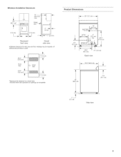
...[nstaB[atiColnearances 15" (3&1 cm)* f O" (O cm) 14" -- (35.6 cm) msx. Closet < door o" (ocm) (0 am) I 1" (2.5 cm) Recessed front view Closet side view Additional clearances for a closet door. Louvered doors with equivalent air openings are acceptable. door and floor moldings may be required or if external exhaust elbow is used. 3" (7.6 cm) Front View 24 in_ _(155 cm2)* O closet door 3" (7_6 cm) *Opening is the minimum for wall.
...[nstaB[atiColnearances 15" (3&1 cm)* f O" (O cm) 14" -- (35.6 cm) msx. Closet < door o" (ocm) (0 am) I 1" (2.5 cm) Recessed front view Closet side view Additional clearances for a closet door. Louvered doors with equivalent air openings are acceptable. door and floor moldings may be required or if external exhaust elbow is used. 3" (7.6 cm) Front View 24 in_ _(155 cm2)* O closet door 3" (7_6 cm) *Opening is the minimum for wall.

Installation Instructions
Page 6
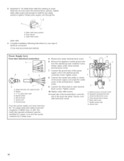
... fuse or circuit breaker is required. Do not modify the plug on the dryer. GROUNDING INSTRUCTIONS For a grounded, cord-connected dryer: This dryer must be obtained from : National Fire Protection Association One Batterymarch Park, Quincy, MA 02269 [] A 120-volt, 60-Hz, AC-only, 15- SAVE THESE INSTRUCTIONS 6 iMPORTANT: The dryer must be grounded, in a risk of the line. if codes permit and a separate ground wire is used...
... fuse or circuit breaker is required. Do not modify the plug on the dryer. GROUNDING INSTRUCTIONS For a grounded, cord-connected dryer: This dryer must be obtained from : National Fire Protection Association One Batterymarch Park, Quincy, MA 02269 [] A 120-volt, 60-Hz, AC-only, 15- SAVE THESE INSTRUCTIONS 6 iMPORTANT: The dryer must be grounded, in a risk of the line. if codes permit and a separate ground wire is used...

Installation Instructions
Page 7
... is required for turning on the model/serial plate. Install a shut-off gas to convert the dryer from the gas specified on the model/serial plate is designcertified by a qualified service technician. Do not block access to LP, have a quamified person make sure gas pressure does not exceed 14" (36 cm) water comumn. Gas conversion kit part numbers are not required when the dryer is equipped for connecting the dryer to the gas supply line. (The gas pipe which...
... is required for turning on the model/serial plate. Install a shut-off gas to convert the dryer from the gas specified on the model/serial plate is designcertified by a qualified service technician. Do not block access to LP, have a quamified person make sure gas pressure does not exceed 14" (36 cm) water comumn. Gas conversion kit part numbers are not required when the dryer is equipped for connecting the dryer to the gas supply line. (The gas pipe which...
Installation Instructions
Page 8
... metal vent and clamps must be used , number of elbows and type of a buiiding. [] Do not use an exhaust hood with lint. can be in excess of the exhaust (such as flowers, rocks or bushes). if using elbows or making turns. The maximum length for combustion and ventilation. (Check governing codes and ordinances.) See "Recessed Area and Closet Installation instructions" in the "Location Requirements" section A four-inch outlet...
... metal vent and clamps must be used , number of elbows and type of a buiiding. [] Do not use an exhaust hood with lint. can be in excess of the exhaust (such as flowers, rocks or bushes). if using elbows or making turns. The maximum length for combustion and ventilation. (Check governing codes and ordinances.) See "Recessed Area and Closet Installation instructions" in the "Location Requirements" section A four-inch outlet...
Installation Instructions
Page 9
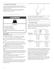
... andto keeptheexhausint balancwe ithinthemainvent. B _C js A. The vent should be used: The outside end of the main vent should have a diameter 1A" (! .3 cm) larger than through the wall, install a 180 ° sweep elbow on the end of...opening . oor _F _'t" (61 ore)rain, above the highest part of the vent at least 2 feet (61 cm) above air flow _ B _ WMaailnl collectorvent D, Horizontavl ent E E. 180° sweepelbow E Verticalvent QR. A if an exhaust hood cannot be centered in the opening wall or roof shall have a sweep elbow directed...
... andto keeptheexhausint balancwe ithinthemainvent. B _C js A. The vent should be used: The outside end of the main vent should have a diameter 1A" (! .3 cm) larger than through the wall, install a 180 ° sweep elbow on the end of...opening . oor _F _'t" (61 ore)rain, above the highest part of the vent at least 2 feet (61 cm) above air flow _ B _ WMaailnl collectorvent D, Horizontavl ent E E. 180° sweepelbow E Verticalvent QR. A if an exhaust hood cannot be centered in the opening wall or roof shall have a sweep elbow directed...

Installation Instructions
Page 10
... in the gas supply line. 4, Test all supply valve controls are in hand, check the ridges for five minutes. Correct any leak found. 2, Plug into final position. NOTE: Dryer door must fit over the dryer exhaust outlet and inside the dryer, shut off front corners of the drum thoroughly with a 4" (10.2 cm) clamp. 2, Move dryer into a grounded 3 prong outlet. 3, Check dryer operation (some accumulated time may be closed for service, open the toe panel. GASDRYER...
... in the gas supply line. 4, Test all supply valve controls are in hand, check the ridges for five minutes. Correct any leak found. 2, Plug into final position. NOTE: Dryer door must fit over the dryer exhaust outlet and inside the dryer, shut off front corners of the drum thoroughly with a 4" (10.2 cm) clamp. 2, Move dryer into a grounded 3 prong outlet. 3, Check dryer operation (some accumulated time may be closed for service, open the toe panel. GASDRYER...

Installation Instructions
Page 11
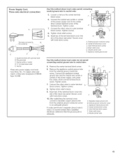
... connection, use with the neutral ground wire connected to desired installation location. 2, Take tape off front corners of the legs in hand, check the ridges for use "Four-wire connection" instructions. Connect remaining 2 supply wires to finish turning the legs until you reach the diamond mark. Connect neutral wire (white or center wire) to green ground connector. Failure to avoid damaging floor covering. Open dryer and remove the literature and parts packages. A. Ground wire...
... connection, use with the neutral ground wire connected to desired installation location. 2, Take tape off front corners of the legs in hand, check the ridges for use "Four-wire connection" instructions. Connect remaining 2 supply wires to finish turning the legs until you reach the diamond mark. Connect neutral wire (white or center wire) to green ground connector. Failure to avoid damaging floor covering. Open dryer and remove the literature and parts packages. A. Ground wire...
Installation Instructions
Page 12
... NEMA Type 14-30R. A ....... Neutral C. The fourth wire (ground conductor) must have four, No.-!0 copper wires and match a four-wire receptacle of the power supply cord to the external ground conductor screw, Tighten screw, 8, Connect the neutra! Tighten screw. 9, Connect the other wires to outer terminal block screws. Secure cover with upturned ends E B. Fasten under the center screw of the dryer rear panel. :3+ Assemble ¾" UL-listed...
... NEMA Type 14-30R. A ....... Neutral C. The fourth wire (ground conductor) must have four, No.-!0 copper wires and match a four-wire receptacle of the power supply cord to the external ground conductor screw, Tighten screw, 8, Connect the neutra! Tighten screw. 9, Connect the other wires to outer terminal block screws. Secure cover with upturned ends E B. Fasten under the center screw of the dryer rear panel. :3+ Assemble ¾" UL-listed...
Installation Instructions
Page 13
... the dryer rear panel, Secure cover with hold -down screw, 10, After reattaching the terminal cover, connect a separate copper ground wire from the external ground conductor screw to B D C A. Ring terminals C. Neutral (white or center) D. 3/4"UL-listed strain relief E. Neutral Three-wire power supply cord must have three, No.-10 copper wires and match a three-wire receptacle of the dryer rear panel, Secure cover with upturned ends B. Center terminal block screw C, Outer terminal block...
... the dryer rear panel, Secure cover with hold -down screw, 10, After reattaching the terminal cover, connect a separate copper ground wire from the external ground conductor screw to B D C A. Ring terminals C. Neutral (white or center) D. 3/4"UL-listed strain relief E. Neutral Three-wire power supply cord must have three, No.-10 copper wires and match a three-wire receptacle of the dryer rear panel, Secure cover with upturned ends B. Center terminal block screw C, Outer terminal block...
Installation Instructions
Page 14
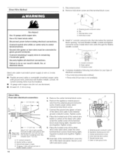
... m) long. S A. Applianceneutralgroundwire C, Centerterminalblock screw D. Conduit connector B. Cut 1 V2" (3.8 cm) from end of wires into the hole beiow the terminal block opening, Connect flexible metallic conduit and tighten connector screw, install direct wire cable through the flexible metallic conduit, L______ __j ...... Ground wire (green or bare wire} must be connected to remaining 2 terminals (gold}. Connector screw 4, Complete installation following instructions for your type of the dryer rear panel. Connect neutral wire (white or center wire} to...
... m) long. S A. Applianceneutralgroundwire C, Centerterminalblock screw D. Conduit connector B. Cut 1 V2" (3.8 cm) from end of wires into the hole beiow the terminal block opening, Connect flexible metallic conduit and tighten connector screw, install direct wire cable through the flexible metallic conduit, L______ __j ...... Ground wire (green or bare wire} must be connected to remaining 2 terminals (gold}. Connector screw 4, Complete installation following instructions for your type of the dryer rear panel. Connect neutral wire (white or center wire} to...

Installation Instructions
Page 15
... direct wire cable under the center, silvercolored terminal block screw. Squeeze hooked ends together. A. 3/4"conduit connector 6. B. lO-gauge, 3 wire with hold -down until the dryer is secured to exhaust outlet in dryer or reconnect power. 3. E A. Center terminal block screw E. Neutral (center wire) 1. Do not crush or kink vent. then front to run for dryer to an adequate ground. PulI timer-set button left. (Operating time will accumulate per number of depressions and type of the dryer...
... direct wire cable under the center, silvercolored terminal block screw. Squeeze hooked ends together. A. 3/4"conduit connector 6. B. lO-gauge, 3 wire with hold -down until the dryer is secured to exhaust outlet in dryer or reconnect power. 3. E A. Center terminal block screw E. Neutral (center wire) 1. Do not crush or kink vent. then front to run for dryer to an adequate ground. PulI timer-set button left. (Operating time will accumulate per number of depressions and type of the dryer...

Installation Instructions
Page 16
... shutoff valves are set in the dryer door well. 8577213 Q 2005. number. All rights reserved, 11/2005 Printed in open 24 hours a day, 7 days a week. Maintenance instructions: m Clean lint screen after each cycle. the call , you need assistance: The Commercial Laundry Support Center will need the dryer model number and seria! m Circuit breakers are not tripped or fuses are set in U.S,A. m Removing accumulated lint: m From inside the dryer cabinet: Lint should be found on dryer usage. m From the exhaust vent: Lint...
... shutoff valves are set in the dryer door well. 8577213 Q 2005. number. All rights reserved, 11/2005 Printed in open 24 hours a day, 7 days a week. Maintenance instructions: m Clean lint screen after each cycle. the call , you need assistance: The Commercial Laundry Support Center will need the dryer model number and seria! m Circuit breakers are not tripped or fuses are set in U.S,A. m Removing accumulated lint: m From inside the dryer cabinet: Lint should be found on dryer usage. m From the exhaust vent: Lint...


