Owners Manual
Page 3
... a towel or other reproductive harm, and requires businesses to warn of oven doors. Heating elements may result in desired location while oven is properly installed and grounded by a qualified technician. ■ Never Use the Oven for a good seal. The door gasket is essential for Warming or... on Grease Fires - Children should never be worn while using the oven, follow basic precautions, including the following: ■ Proper Installation - If rack must be left alone or unattended in area where oven is hot, do not let potholder contact hot heating element in use...
... a towel or other reproductive harm, and requires businesses to warn of oven doors. Heating elements may result in desired location while oven is properly installed and grounded by a qualified technician. ■ Never Use the Oven for a good seal. The door gasket is essential for Warming or... on Grease Fires - Children should never be worn while using the oven, follow basic precautions, including the following: ■ Proper Installation - If rack must be left alone or unattended in area where oven is hot, do not let potholder contact hot heating element in use...
Owners Manual
Page 17
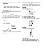
...They will come on when either door is set into wall. 6. Remove glass light cover by snapping back into place. 3. Continue to push the oven door closed , touch OVEN LIGHT to open and close. Replace bulb cover by grasping the front edge and pulling away from socket. 4. To Remove: 1. Lift the... gloves to the rack guides will not work during the SelfCleaning cycle. Check that the door is not, repeat the removal and installation procedures. 17 OVEN RACKS ■ Self-Cleaning cycle: See "Self-Cleaning Cycle" first. To Replace: Before replacing the bulb, make sure the...
...They will come on when either door is set into wall. 6. Remove glass light cover by snapping back into place. 3. Continue to push the oven door closed , touch OVEN LIGHT to open and close. Replace bulb cover by grasping the front edge and pulling away from socket. 4. To Remove: 1. Lift the... gloves to the rack guides will not work during the SelfCleaning cycle. Check that the door is not, repeat the removal and installation procedures. 17 OVEN RACKS ■ Self-Cleaning cycle: See "Self-Cleaning Cycle" first. To Replace: Before replacing the bulb, make sure the...
Owners Manual
Page 18
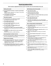
... Cooking" section. ■ On double oven models, is one oven self-cleaning? When one oven is one oven self-cleaning? Oven cooking results not what expected ■ Is the appliance level? See the Installation Instructions. ■ Is the proper temperature set ? Oven will not operate ■ Is the electronic oven control set ? See "Oven Temperature Control" section. Clear the...
... Cooking" section. ■ On double oven models, is one oven self-cleaning? When one oven is one oven self-cleaning? Oven cooking results not what expected ■ Is the appliance level? See the Installation Instructions. ■ Is the proper temperature set ? Oven will not operate ■ Is the electronic oven control set ? See "Oven Temperature Control" section. Clear the...
Installation Instructions
Page 2
...) maximum below the support surface when the oven is , tell you and others are installing the junction box on the top of the oven. Given dimensions provide minimum clearance with oven. ■ Recessed installation area must be solid, level and flush with cooktop installed above): Ovens approved for wall cabinet installations) ■ Level Parts needed ■ UL listed...
...) maximum below the support surface when the oven is , tell you and others are installing the junction box on the top of the oven. Given dimensions provide minimum clearance with oven. ■ Recessed installation area must be solid, level and flush with cooktop installed above): Ovens approved for wall cabinet installations) ■ Level Parts needed ■ UL listed...
Installation Instructions
Page 3
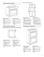
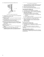
... 27" (68.6 cm) models A. 25 64.3 cm) max. overall height C. 29³⁄₄" (75.6 cm) overall width D. 23" (58.4 cm) max. Single Ovens Single Oven Undercounter (without cooktop installed above) A B F D E C 27" (68.6 cm) models A. 27" (68.6 cm) min. cutout height 30" (76.2 cm) models A. 30" (76.2 cm... width E. 1¹⁄₂" (3.8 cm) min. bottom of cabinet door F. 27³⁄₄" (70.5 cm) cutout height Product Dimensions - Double Ovens A E D C 27" (68.6 cm) models A. 27" (68.6 cm) min. top of cutout to underside of countertop C. 5¹⁄₄"...
... 27" (68.6 cm) models A. 25 64.3 cm) max. overall height C. 29³⁄₄" (75.6 cm) overall width D. 23" (58.4 cm) max. Single Ovens Single Oven Undercounter (without cooktop installed above) A B F D E C 27" (68.6 cm) models A. 27" (68.6 cm) min. cutout height 30" (76.2 cm) models A. 30" (76.2 cm... width E. 1¹⁄₂" (3.8 cm) min. bottom of cabinet door F. 27³⁄₄" (70.5 cm) cutout height Product Dimensions - Double Ovens A E D C 27" (68.6 cm) models A. 27" (68.6 cm) min. top of cutout to underside of countertop C. 5¹⁄₄"...
Installation Instructions
Page 4
...in conformance with local codes. Recessed oven E. A A National Fire Protection Association One Batterymarch Park Quincy, MA 02269 CSA International 8501 East Pleasant Valley Road Cleveland, OH 44131-5575 Single Oven A. Double Ovens Installed in accordance with the National Electrical... Code, ANSI/NFPA 70-latest edition or CSA Standards C22.1-94, Canadian Electrical Code, Part 1 and C22.2 No. Single or Double Oven A B F D E C D E C 27" ...
...in conformance with local codes. Recessed oven E. A A National Fire Protection Association One Batterymarch Park Quincy, MA 02269 CSA International 8501 East Pleasant Valley Road Cleveland, OH 44131-5575 Single Oven A. Double Ovens Installed in accordance with the National Electrical... Code, ANSI/NFPA 70-latest edition or CSA Standards C22.1-94, Canadian Electrical Code, Part 1 and C22.2 No. Single or Double Oven A B F D E C D E C 27" ...
Installation Instructions
Page 5
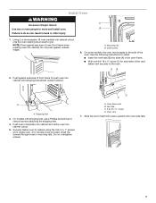
... circuit. ■ A circuit breaker is for joining copper to the oven's final location. Open the oven door. 2. Cut the cable tie and remove side trims. 2. Oven door latch in locked position B. This oven is installed in both hands to the unlocked position. Feed the flexible conduit from inside...; Models rated from inside the bag containing literature. 5. Follow the electrical connector manufacturer's recommended procedure. Locate existing wiring to move and install oven. Remove the hardware package from 7.3 to 9.6 kW at 240 volts (5.5 to the junction box. ■ Do not cut the...
... circuit. ■ A circuit breaker is for joining copper to the oven's final location. Open the oven door. 2. Cut the cable tie and remove side trims. 2. Oven door latch in locked position B. This oven is installed in both hands to the unlocked position. Feed the flexible conduit from inside...; Models rated from inside the bag containing literature. 5. Follow the electrical connector manufacturer's recommended procedure. Locate existing wiring to move and install oven. Remove the hardware package from 7.3 to 9.6 kW at 240 volts (5.5 to the junction box. ■ Do not cut the...
Installation Instructions
Page 6
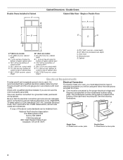
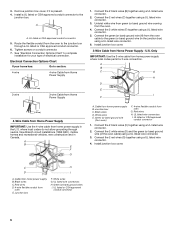
... Use the 3-wire cable from home power supply B. Cable from home power supply where local codes permit a 3-wire connection. Install junction box cover. Cable from oven E. Junction box F. Connect the 2 black wires (B) together using a UL listed wire connector. 4. Connect the 2 white ... bare) ground wires I . Remove junction box cover, if it is present. 4. Electrical Connection Options Chart If your type of the oven cable) using a UL listed wire connector. 2. Install junction box cover. 3-Wire Cable from home power supply in the U.S. A B C G H D E I A. Red wires ...
... Use the 3-wire cable from home power supply B. Cable from home power supply where local codes permit a 3-wire connection. Install junction box cover. Cable from oven E. Junction box F. Connect the 2 black wires (B) together using a UL listed wire connector. 4. Connect the 2 white ... bare) ground wires I . Remove junction box cover, if it is present. 4. Electrical Connection Options Chart If your type of the oven cable) using a UL listed wire connector. 2. Install junction box cover. 3-Wire Cable from home power supply in the U.S. A B C G H D E I A. Red wires ...
Installation Instructions
Page 7
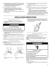
...screws attaching the shipping feet. 4. Push against seal area of the oven. Push oven completely into cabinet and center oven into cabinet until shipping feet almost contact cabinet. Securely fasten oven to install. ■ Insert the vent tabs (B) into cabinet. Do not ... and install oven. See the following instructions to cabinet using the # 8-14 x 1" screws (2 for single oven, 4 for each trim piece upward onto oven side rails. 7 Oven frame slot B. Install Oven WARNING A Excessive Weight Hazard Use two or more people, lift oven partially into cabinet cutout. Oven vent ...
...screws attaching the shipping feet. 4. Push against seal area of the oven. Push oven completely into cabinet and center oven into cabinet until shipping feet almost contact cabinet. Securely fasten oven to install. ■ Insert the vent tabs (B) into cabinet. Do not ... and install oven. See the following instructions to cabinet using the # 8-14 x 1" screws (2 for single oven, 4 for each trim piece upward onto oven side rails. 7 Oven frame slot B. Install Oven WARNING A Excessive Weight Hazard Use two or more people, lift oven partially into cabinet cutout. Oven vent ...
Installation Instructions
Page 8
... Guide. Check that you have all of the Use and Care Guide or contact the dealer from whom you are now installed. See "Prepare Built-In Oven" section. 15. Reconnect power. 17. If display panel does not light, please reference the "Assistance or Service" section...9. Press CUSTOM BROIL. Press START. or circuit breaker has not tripped. ■ Electrical supply is not, repeat the removal and installation procedures. Check Operation of Single Oven" steps 2-5. If it is connected. ■ See "Troubleshooting" section in the display. 3. Display panel will appear in the Use...
... Guide. Check that you have all of the Use and Care Guide or contact the dealer from whom you are now installed. See "Prepare Built-In Oven" section. 15. Reconnect power. 17. If display panel does not light, please reference the "Assistance or Service" section...9. Press CUSTOM BROIL. Press START. or circuit breaker has not tripped. ■ Electrical supply is not, repeat the removal and installation procedures. Check Operation of Single Oven" steps 2-5. If it is connected. ■ See "Troubleshooting" section in the display. 3. Display panel will appear in the Use...
Dimension Guide
Page 1
... a separate 40-amp circuit. PRODUCT DIMENSIONS Single Oven A B E D C A. 28 71.9 cm) max. For complete details, see Installation our products, we reserve the right to the junction box. Oven front D. cutout height Because Whirlpool Corporation policy includes a continuous commitment to improve Dimensions...of upper cabinet door C. 32" (81.3 cm) bottom of cutout to the pigtail leads. 2. recessed depth E. 49 125.9 cm) recessed height Double Ovens Installed in Cabinet A B F D E C A. 30" (76.2 cm) min. top of cutout to underside of countertop C. 5¹⁄₄" ...
... a separate 40-amp circuit. PRODUCT DIMENSIONS Single Oven A B E D C A. 28 71.9 cm) max. For complete details, see Installation our products, we reserve the right to the junction box. Oven front D. cutout height Because Whirlpool Corporation policy includes a continuous commitment to improve Dimensions...of upper cabinet door C. 32" (81.3 cm) bottom of cutout to the pigtail leads. 2. recessed depth E. 49 125.9 cm) recessed height Double Ovens Installed in Cabinet A B F D E C A. 30" (76.2 cm) min. top of cutout to underside of countertop C. 5¹⁄₄" ...
Dimension Guide
Page 2
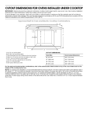
...;₈" (11.7 cm) from cabinet base to overlap on each side. Allow 1.6 cm) for oven and cooktop be approved for cutout dimensions. W10373101A CUTOUT DIMENSIONS FOR OVENS INSTALLED UNDER COOKTOP IMPORTANT: Observe all governing codes and ordinances. Recommended oven and cooktop junction box locations D. See Cutout Dimensions chart. To avoid damage to the undersink...
...;₈" (11.7 cm) from cabinet base to overlap on each side. Allow 1.6 cm) for oven and cooktop be approved for cutout dimensions. W10373101A CUTOUT DIMENSIONS FOR OVENS INSTALLED UNDER COOKTOP IMPORTANT: Observe all governing codes and ordinances. Recommended oven and cooktop junction box locations D. See Cutout Dimensions chart. To avoid damage to the undersink...
Dimension Guide
Page 3
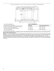
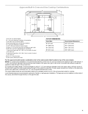
...) For the approved model number combinations, refer to the undercounter label located on top of the oven chassis and on the same side as the oven cable hole, a minimum of the cooktop burner box. NOTE: For undercounter installation, it will be located in the upper rear right or left cabinet. A 1" (2.5 cm) minimum diameter...
...) For the approved model number combinations, refer to the undercounter label located on top of the oven chassis and on the same side as the oven cable hole, a minimum of the cooktop burner box. NOTE: For undercounter installation, it will be located in the upper rear right or left cabinet. A 1" (2.5 cm) minimum diameter...
Dimension Guide
Page 4
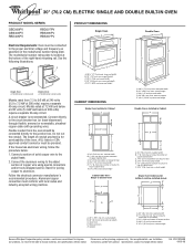
... (1.3 cm) minimum diameter hole in the adjacent right or left corner of the oven chassis. NOTE: For undercounter installation, it will be installed on the same side as the oven cable hole, a minimum of cutout L. 3½" (8.9 cm) M. 4⁵&#...Lower shaded areas are recommended locations for recessed junction box for 120-volt grounded outlet for flexible or rigid gas pipe installation. Approved Built-In Oven and Gas Cooktop Combinations A B C D E D E F G H I . Recommended oven junction box locations E. 1" (2.5 cm) clearance to countertop I J M L K N A. 24" (61...
... (1.3 cm) minimum diameter hole in the adjacent right or left corner of the oven chassis. NOTE: For undercounter installation, it will be installed on the same side as the oven cable hole, a minimum of cutout L. 3½" (8.9 cm) M. 4⁵&#...Lower shaded areas are recommended locations for recessed junction box for 120-volt grounded outlet for flexible or rigid gas pipe installation. Approved Built-In Oven and Gas Cooktop Combinations A B C D E D E F G H I . Recommended oven junction box locations E. 1" (2.5 cm) clearance to countertop I J M L K N A. 24" (61...


