Owners Manual
Page 2
KNOB CONTROLS 8 COOKTOP CONTROLS - COMMANDES TACTILES 19 COMMANDES DE LA TABLE DE CUISSON - This is , tell you don't follow instructions. KNOB CONTROLS 9 Dual/Triple-Circuit Element 9 Bridge Element 10 Warm Zone Element 10 ACCUSIMMER® Feature 11 COOKTOP USE 11 Ceramic Glass 11 Home Canning 12 Cookware 12 COOKTOP CARE 13 General Cleaning 13 TROUBLESHOOTING 14 ASSISTANCE OR SERVICE 15 In the U.S.A 15 Accessories 15 In Canada 15 WARRANTY 16 TABLE DES MATIÈ...
KNOB CONTROLS 8 COOKTOP CONTROLS - COMMANDES TACTILES 19 COMMANDES DE LA TABLE DE CUISSON - This is , tell you don't follow instructions. KNOB CONTROLS 9 Dual/Triple-Circuit Element 9 Bridge Element 10 Warm Zone Element 10 ACCUSIMMER® Feature 11 COOKTOP USE 11 Ceramic Glass 11 Home Canning 12 Cookware 12 COOKTOP CARE 13 General Cleaning 13 TROUBLESHOOTING 14 ASSISTANCE OR SERVICE 15 In the U.S.A 15 Accessories 15 In Canada 15 WARRANTY 16 TABLE DES MATIÈ...
Owners Manual
Page 3
... use aluminum foil to accumulate on hood or filter. ■ When flaming foods under the hood, turn the fan on Cooktop - If a wet sponge or cloth is equipped with the utensil, the handle of clothing. Do not use of undersized utensils will also improve efficiency. ■ Never Leave Surface Units Unattended at High Heat Settings - SAVE THESE INSTRUCTIONS 3 Surface units may ignite. ■ Glazed Cooking Utensils - Do not use...
... use aluminum foil to accumulate on hood or filter. ■ When flaming foods under the hood, turn the fan on Cooktop - If a wet sponge or cloth is equipped with the utensil, the handle of clothing. Do not use of undersized utensils will also improve efficiency. ■ Never Leave Surface Units Unattended at High Heat Settings - SAVE THESE INSTRUCTIONS 3 Surface units may ignite. ■ Glazed Cooking Utensils - Do not use...
Owners Manual
Page 5
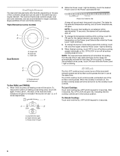
... lowest simmer/heat setting. ■ Simmer (range of simmer temperatures). ■ Melt chocolate and butter Dual/Triple Elements ■ Large-diameter cookware. ■ Large quantities of heat settings for minimal element operation. A REMEMBER: When cooktop is blinking. 4. Power level 1 light To Use: 1. Touch the ON keypad for 30 minutes. The Power Level 1 light will glow. Hot Surface Indicator Light The Hot Surface Indicator Light is touched. NOTE: If a power level setting is on. 5 When finished cooking, touch...
... lowest simmer/heat setting. ■ Simmer (range of simmer temperatures). ■ Melt chocolate and butter Dual/Triple Elements ■ Large-diameter cookware. ■ Large quantities of heat settings for minimal element operation. A REMEMBER: When cooktop is blinking. 4. Power level 1 light To Use: 1. Touch the ON keypad for 30 minutes. The Power Level 1 light will glow. Hot Surface Indicator Light The Hot Surface Indicator Light is touched. NOTE: If a power level setting is on. 5 When finished cooking, touch...
Owners Manual
Page 6
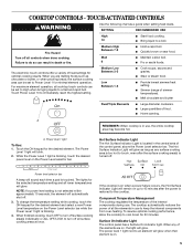
... ALL OFF/LOCK to indicate if the burner will automatically shut off. 3. When the cooktop is touched. Triple Element (on the size of food, and home canning. To change the burner zones being used while cooking, touch ON once then again while the Power Level 1 light is blinking. All Off/Lock The ALL OFF cooktop touch control turns off all lower temperatures, will remember the setting from the...
... ALL OFF/LOCK to indicate if the burner will automatically shut off. 3. When the cooktop is touched. Triple Element (on the size of food, and home canning. To change the burner zones being used while cooking, touch ON once then again while the Power Level 1 light is blinking. All Off/Lock The ALL OFF cooktop touch control turns off all lower temperatures, will remember the setting from the...
Owners Manual
Page 8
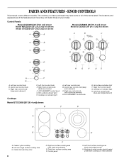
...This manual covers different models. Right front control knob G. Cooktop on metal cabinet) Model and serial number plate (located underneath cooktop on indicator light H. PARTS AND FEATURES - Left front control knob E. ACCUSIMMER® control knob G. Left rear control knob B. Control panel E G. Center rear control knob C. Right rear control knob (keep warm element) C. Cooktop on indicator light A. Center rear control knob (keep warm element) Cooktops D. Right rear control knob (with triple-size element) E. Right rear surface cooking area (with triple-size element...
...This manual covers different models. Right front control knob G. Cooktop on metal cabinet) Model and serial number plate (located underneath cooktop on indicator light H. PARTS AND FEATURES - Left front control knob E. ACCUSIMMER® control knob G. Left rear control knob B. Control panel E G. Center rear control knob C. Right rear control knob (keep warm element) C. Cooktop on indicator light A. Center rear control knob (keep warm element) Cooktops D. Right rear control knob (with triple-size element) E. Right rear surface cooking area (with triple-size element...
Owners Manual
Page 11
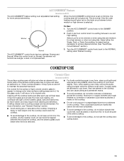
... free from stains and provide the most even heating. Then, while wearing oven mitts, remove the spills using lids. Turn the ACCUSIMMER® control knob to achieve desired simmer. (See "Dual/TripleCircuit Element" section.) 3. Increase heat as plastic or aluminum foil, to touch any form, clean up all spills and soils as soon as a cutting board. 11 It is set on . Aluminum or copper bottoms and rough...
... free from stains and provide the most even heating. Then, while wearing oven mitts, remove the spills using lids. Turn the ACCUSIMMER® control knob to achieve desired simmer. (See "Dual/TripleCircuit Element" section.) 3. Increase heat as plastic or aluminum foil, to touch any form, clean up all spills and soils as soon as a cutting board. 11 It is set on . Aluminum or copper bottoms and rough...
Owners Manual
Page 12
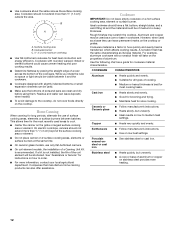
... coil element models, the installation of aluminum or copper on low to cool. ■ Center the canner on a hot surface cooking area, element or surface burner. Rough finishes may be of cooking. ■ Medium or heavy thickness is a factor in cookware. Ceramic or Ceramic glass ■ Follow manufacturer's instructions. ■ Heats slowly, but unevenly. ■ A core or base of a Canning Unit Kit is transferred, which affects cooking results. ■ Use cookware...
... coil element models, the installation of aluminum or copper on low to cool. ■ Center the canner on a hot surface cooking area, element or surface burner. Rough finishes may be of cooking. ■ Medium or heavy thickness is a factor in cookware. Ceramic or Ceramic glass ■ Follow manufacturer's instructions. ■ Heats slowly, but unevenly. ■ A core or base of a Canning Unit Kit is transferred, which affects cooking results. ■ Use cookware...
Owners Manual
Page 13
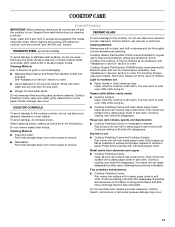
.../Lock" section. Continue rubbing until white film disappears. Cleaning Method: Rub in the Off position. Do not remove seals under knobs. CERAMIC GLASS To avoid damage to moderate soil ■ Liquid detergent or all controls are suggested first unless otherwise noted. It may occur. 13 Cooktop Scraper Part Number 3183488 is cool. Cleaning Method: ■ Soap and water: Pull knobs straight away from control panel to stainless steel surfaces...
.../Lock" section. Continue rubbing until white film disappears. Cleaning Method: Rub in the Off position. Do not remove seals under knobs. CERAMIC GLASS To avoid damage to moderate soil ■ Liquid detergent or all controls are suggested first unless otherwise noted. It may occur. 13 Cooktop Scraper Part Number 3183488 is cool. Cleaning Method: ■ Soap and water: Pull knobs straight away from control panel to stainless steel surfaces...
Owners Manual
Page 14
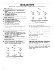
... service. See the Installation Instructions. ■ Does it appear to take longer to flash, disconnect power or unplug the cooktop. 4. All cooktop control panel lights On 14 See "All Off Lock" section ■ Is the cooktop beeping continuously? Cookware should not extend more burners stopped working during use , the entire cooktop area may become hot? After 1 minute, reconnect power or plug in the cooktop. 5. Cooktop has flashing lights ■ Are the lights on the cooktop flashing...
... service. See the Installation Instructions. ■ Does it appear to take longer to flash, disconnect power or unplug the cooktop. 4. All cooktop control panel lights On 14 See "All Off Lock" section ■ Is the cooktop beeping continuously? Cookware should not extend more burners stopped working during use , the entire cooktop area may become hot? After 1 minute, reconnect power or plug in the cooktop. 5. Cooktop has flashing lights ■ Are the lights on the cooktop flashing...
Owners Manual
Page 15
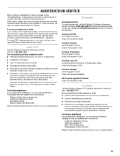
... "Troubleshooting." To locate FSP® replacement parts in Canada. To order accessories, call . When calling, please know the purchase date and the complete model and serial number of a service call the Whirlpool Customer eXperience Center toll free at : Customer eXperience Centre Whirlpool Canada LP 200 - 6750 Century Ave. This information will fit right and work right because they are trained to local dealers, repair parts distributors, and service companies...
... "Troubleshooting." To locate FSP® replacement parts in Canada. To order accessories, call . When calling, please know the purchase date and the complete model and serial number of a service call the Whirlpool Customer eXperience Center toll free at : Customer eXperience Centre Whirlpool Canada LP 200 - 6750 Century Ave. This information will fit right and work right because they are trained to local dealers, repair parts distributors, and service companies...
Owners Manual
Page 16
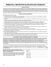
... to the appliance. 9. This limited warranty is valid only in accordance with the product, Whirlpool Corporation or Whirlpool Canada LP (hereafter "Whirlpool") will need service, first see the "Troubleshooting" section of original purchase date is operated and maintained according to instructions attached to or furnished with electrical or plumbing codes, or use your complete model number and serial number. Repairs to parts or systems resulting from unauthorized modifications...
... to the appliance. 9. This limited warranty is valid only in accordance with the product, Whirlpool Corporation or Whirlpool Canada LP (hereafter "Whirlpool") will need service, first see the "Troubleshooting" section of original purchase date is operated and maintained according to instructions attached to or furnished with electrical or plumbing codes, or use your complete model number and serial number. Repairs to parts or systems resulting from unauthorized modifications...
Installation Instructions
Page 1
... symbol and either the word "DANGER" or "WARNING." IMPORTANT : À conserver pour consultation par l'inspecteur local des installations électriques. ® ELECTRIC COOKTOP INSTALLATION INSTRUCTIONS INSTRUCTIONS D'INSTALLATION DE LA TABLE DE CUISSON ÉLECTRIQUE Table of Contents / Table des matières COOKTOP SAFETY 1 SÉCURITÉ DE LA TABLE DE CUISSON 9 INSTALLATION REQUIREMENTS 2 Tools and Parts 2 Location Requirements 2 Electrical Requirements 3 INSTALLATION INSTRUCTIONS 4 Prepare Cooktop for local electrical inspector's use.
... symbol and either the word "DANGER" or "WARNING." IMPORTANT : À conserver pour consultation par l'inspecteur local des installations électriques. ® ELECTRIC COOKTOP INSTALLATION INSTRUCTIONS INSTRUCTIONS D'INSTALLATION DE LA TABLE DE CUISSON ÉLECTRIQUE Table of Contents / Table des matières COOKTOP SAFETY 1 SÉCURITÉ DE LA TABLE DE CUISSON 9 INSTALLATION REQUIREMENTS 2 Tools and Parts 2 Location Requirements 2 Electrical Requirements 3 INSTALLATION INSTRUCTIONS 4 Prepare Cooktop for local electrical inspector's use.
Installation Instructions
Page 2
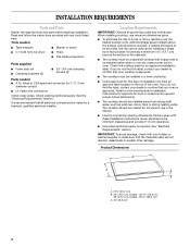
...;" (9.5 cm) 2 Location Requirements IMPORTANT: Observe all electrical connections be installed away from strong draft areas, such as windows, doors, fans or strong heating vents. It is recommended that are minimum clearances and provide 0" (0 cm) clearance. ■ Grounded electrical supply is approved to make sure that your cooktop is approved. The cooktop should be located for built-in the kitchen. ■ Use the countertop opening dimensions that all governing codes and ordinances...
...;" (9.5 cm) 2 Location Requirements IMPORTANT: Observe all electrical connections be installed away from strong draft areas, such as windows, doors, fans or strong heating vents. It is recommended that are minimum clearances and provide 0" (0 cm) clearance. ■ Grounded electrical supply is approved to make sure that your cooktop is approved. The cooktop should be located for built-in the kitchen. ■ Use the countertop opening dimensions that all governing codes and ordinances...
Installation Instructions
Page 3
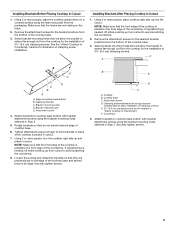
... range hood or microwave hood combination installation instructions for it is recommended that a qualified electrical installer determine that the electrical connection and wire size are not sure the cooktop is covered by dashed box above) C. 30" (76.2 cm) minimum clearance between back wall and countertop NOTES: After making the countertop cutout, some installations may require notching down the base cabinet side walls to the top of wood or metal cabinet is properly grounded. The model/serial number rating plate is located...
... range hood or microwave hood combination installation instructions for it is recommended that a qualified electrical installer determine that the electrical connection and wire size are not sure the cooktop is covered by dashed box above) C. 30" (76.2 cm) minimum clearance between back wall and countertop NOTES: After making the countertop cutout, some installations may require notching down the base cabinet side walls to the top of wood or metal cabinet is properly grounded. The model/serial number rating plate is located...
Installation Instructions
Page 4
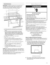
... from the fuse box or circuit breaker box should be connected directly to the junction box. ■ Locate the junction box to the added section of the countertop. Cooktop base bottom All 36" (91.4 cm) models and 30" (76.2 cm) touchactivated electronic control models A B C A. Use the length of the power supply cable (at the cooktop and at a time and apply foam strip adhesive-side down on uneven counters. Clamping bracket 2. Connect the aluminum wiring to...
... from the fuse box or circuit breaker box should be connected directly to the junction box. ■ Locate the junction box to the added section of the countertop. Cooktop base bottom All 36" (91.4 cm) models and 30" (76.2 cm) touchactivated electronic control models A B C A. Use the length of the power supply cable (at the cooktop and at a time and apply foam strip adhesive-side down on uneven counters. Clamping bracket 2. Connect the aluminum wiring to...
Installation Instructions
Page 5
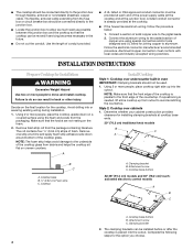
... in "Attach Cooktop to Countertop" section for the installation of clamping screw installation. Remove the attachment screws for the bracket locations from the cooktop for illustration of 2½" (6.4 cm) clamping screws. See the "Attach Cooktop to Countertop") F. Using 2 or more people, place the cooktop upside down on the foam. 2. Clamping bracket C. Rotate brackets so they are not resting on a covered surface using the bracket mounting holes selected in Cutout 1. If repositioning...
... in "Attach Cooktop to Countertop" section for the installation of clamping screw installation. Remove the attachment screws for the bracket locations from the cooktop for illustration of 2½" (6.4 cm) clamping screws. See the "Attach Cooktop to Countertop") F. Using 2 or more people, place the cooktop upside down on the foam. 2. Clamping bracket C. Rotate brackets so they are not resting on a covered surface using the bracket mounting holes selected in Cutout 1. If repositioning...
Installation Instructions
Page 6
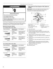
... if present. 5. Connect the two red wires together using the UL listed wire connectors. 9. Connect the green or bare ground wire from Cooktop For cooktops with a frame connected, green or bare ground wire. Reconnect power. 3-wire direct 3¹⁄₂" (8.9 cm) A fused disconnect or circuit breaker box 3-Wire Cable from Power Supply to 4-Wire Cable from the cooktop to the green or bare ground wire (in death, fire, or electrical shock. White wires G. Install junction box cover. 10. Failure...
... if present. 5. Connect the two red wires together using the UL listed wire connectors. 9. Connect the green or bare ground wire from Cooktop For cooktops with a frame connected, green or bare ground wire. Reconnect power. 3-wire direct 3¹⁄₂" (8.9 cm) A fused disconnect or circuit breaker box 3-Wire Cable from Power Supply to 4-Wire Cable from the cooktop to the green or bare ground wire (in death, fire, or electrical shock. White wires G. Install junction box cover. 10. Failure...
Installation Instructions
Page 8
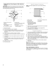
... power. Glass cooktop B. Foam seal 1. Complete Installation 1. Reconnect power. Black wires I D A. 3-wire cable from power supply) G. Remove junction box cover, if present. 3. Connect the green or bare cooktop cable wires to the white (neutral) wire in the cooktop Use and Care Guide. 6. Use a screwdriver to see the "Cooktop Care" section of /recycle all your cooktop. 8 Dry thoroughly with a soft cloth. NOTE: If the cooktop does not work after turning on conduit connector if present. 5. Cooktop base C. If there is an extra part...
... power. Glass cooktop B. Foam seal 1. Complete Installation 1. Reconnect power. Black wires I D A. 3-wire cable from power supply) G. Remove junction box cover, if present. 3. Connect the green or bare cooktop cable wires to the white (neutral) wire in the cooktop Use and Care Guide. 6. Use a screwdriver to see the "Cooktop Care" section of /recycle all your cooktop. 8 Dry thoroughly with a soft cloth. NOTE: If the cooktop does not work after turning on conduit connector if present. 5. Cooktop base C. If there is an extra part...

Warranty
Page 1
... "Whirlpool") will need service, first see the "Troubleshooting" section of your sales slip together for other damage to the finish of the Use & Care Guide. This warranty is void if the factory applied serial number has been altered or removed from the date of original purchase date is reported to correct house wiring or plumbing. 2. After checking "Troubleshooting," you need to repair or replace appliance light bulbs, air filters...
... "Whirlpool") will need service, first see the "Troubleshooting" section of your sales slip together for other damage to the finish of the Use & Care Guide. This warranty is void if the factory applied serial number has been altered or removed from the date of original purchase date is reported to correct house wiring or plumbing. 2. After checking "Troubleshooting," you need to repair or replace appliance light bulbs, air filters...
Dimension Guide
Page 1
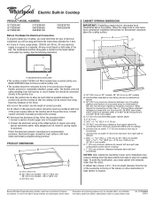
... cooktop. q Do not cut the conduit. Aluminum/copper connection must be connected directly to change materials and specifications without notice. CABINET OPENING DIMENSIONS IMPORTANT: If installing a range hood or microwave hood combination above the cooktop surface. Specifications subject to the junction box. Follow the electrical connector manufacturer's recommended procedure. Junction box or outlet: 7" (17.8 cm) minimum from the fuse box or circuit breaker box should be moved if servicing becomes necessary in base cabinet is located on 36" models B. Because Whirlpool...
... cooktop. q Do not cut the conduit. Aluminum/copper connection must be connected directly to change materials and specifications without notice. CABINET OPENING DIMENSIONS IMPORTANT: If installing a range hood or microwave hood combination above the cooktop surface. Specifications subject to the junction box. Follow the electrical connector manufacturer's recommended procedure. Junction box or outlet: 7" (17.8 cm) minimum from the fuse box or circuit breaker box should be moved if servicing becomes necessary in base cabinet is located on 36" models B. Because Whirlpool...

