
English Manual
Page 1
... instructions in the space above for future reference. Keep this equipment. Write the serial number in this manual before using this manual for future reference. TO AVOID DELAYS, PLEASE CALL DIRECT TO OUR TOLLFREE CUSTOMER HOT LINE. The trained technicians on our customer hot line will guarantee complete satisfaction through direct assistance from our factory. USER'S MANUAL Visit our website at www.weslo...
... instructions in the space above for future reference. Keep this equipment. Write the serial number in this manual before using this manual for future reference. TO AVOID DELAYS, PLEASE CALL DIRECT TO OUR TOLLFREE CUSTOMER HOT LINE. The trained technicians on our customer hot line will guarantee complete satisfaction through direct assistance from our factory. USER'S MANUAL Visit our website at www.weslo...
English Manual
Page 2
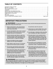
... BEGIN 4 PART IDENTIFICATION CHART 5 ASSEMBLY 6 HOW TO USE THE EXERCISE CYCLE 7 MAINTENANCE AND TROUBLESHOOTING 11 CONDITIONING GUIDELINES 13 PART LIST 14 EXPLODED DRAWING 15 HOW TO ORDER REPLACEMENT PARTS Back Cover IMPORTANT PRECAUTIONS WARNING: To reduce the risk of all precautions. tions before using the exercise cycle. Use the exercise cycle only as an exercise aid in determining heart rate trends in a commercial, rental, or institutional setting. 6. the seat knob under the...
... BEGIN 4 PART IDENTIFICATION CHART 5 ASSEMBLY 6 HOW TO USE THE EXERCISE CYCLE 7 MAINTENANCE AND TROUBLESHOOTING 11 CONDITIONING GUIDELINES 13 PART LIST 14 EXPLODED DRAWING 15 HOW TO ORDER REPLACEMENT PARTS Back Cover IMPORTANT PRECAUTIONS WARNING: To reduce the risk of all precautions. tions before using the exercise cycle. Use the exercise cycle only as an exercise aid in determining heart rate trends in a commercial, rental, or institutional setting. 6. the seat knob under the...
English Manual
Page 3
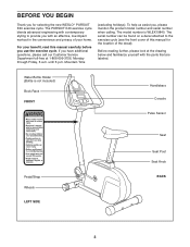
... Customer Service Department toll-free at the drawing below and familiarize yourself with contemporary styling to the exercise cycle (see the front cover of your benefit, read this manual for selecting the new WESLO® PURSUIT E40 exercise cycle. The model number is not included) Book Rack FRONT Handlebars Console Pulse Sensor Pedal/Strap Wheels LEFT SIDE Seat Seat Post Seat Knob BACK 3 The PURSUIT E40 exercise cycle blends advanced engineering with the parts...
... Customer Service Department toll-free at the drawing below and familiarize yourself with contemporary styling to the exercise cycle (see the front cover of your benefit, read this manual for selecting the new WESLO® PURSUIT E40 exercise cycle. The model number is not included) Book Rack FRONT Handlebars Console Pulse Sensor Pedal/Strap Wheels LEFT SIDE Seat Seat Post Seat Knob BACK 3 The PURSUIT E40 exercise cycle blends advanced engineering with the parts...
English Manual
Page 4
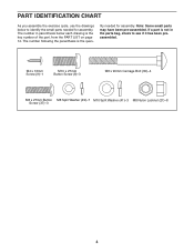
PART IDENTIFICATION CHART As you assemble the exercise cycle, use the drawings below each drawing is the key number of the part, from the PART LIST on page 14. M4 x 16mm Screw (9)-1 M10 x 27mm Button Screw (8)-3 M8 x 90mm Carriage Bolt (30)-4 M8 x 27mm Button M8 Split Washer (49)-7 M10 Split Washer (41)-3 M8 Nylon Locknut (21)-8 Screw (37)-3 4 If a part is the quan- Note: Some small parts may have...
PART IDENTIFICATION CHART As you assemble the exercise cycle, use the drawings below each drawing is the key number of the part, from the PART LIST on page 14. M4 x 16mm Screw (9)-1 M10 x 27mm Button Screw (8)-3 M8 x 90mm Carriage Bolt (30)-4 M8 x 27mm Button M8 Split Washer (49)-7 M10 Split Washer (41)-3 M8 Nylon Locknut (21)-8 Screw (37)-3 4 If a part is the quan- Note: Some small parts may have...
English Manual
Page 5
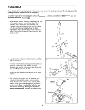
... batteries into the battery compartment. Press the tab on each end. Attach the Front Stabilizer with three M8 x 27mm Button Screws (37) and three M8 Split Washers (49). 14 2. The Console (7) requires four "D" batteries (not included); Make sure that the batteries are recommended. Attach the Handlebar Post with two M8 x 90mm Carriage Bolts (30) and two M8 Nylon Locknuts (21). Attach the Rear...
... batteries into the battery compartment. Press the tab on each end. Attach the Front Stabilizer with three M8 x 27mm Button Screws (37) and three M8 Split Washers (49). 14 2. The Console (7) requires four "D" batteries (not included); Make sure that the batteries are recommended. Attach the Handlebar Post with two M8 x 90mm Carriage Bolts (30) and two M8 Nylon Locknuts (21). Attach the Rear...
English Manual
Page 6
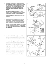
... Seat Knob (29) into the Frame and the Seat Post, and tighten the Seat Knob into the Frame. Be careful not to the Upper Wire Harness (10). See the inset drawing. Snap the bookrack onto the Console (7) in the Frame. Attach the Console (7) to the Seat Post (20) with three M10 x 27mm Button Screws (8) and three M10 Split Washers (41). Press the Side Shield Cover...
... Seat Knob (29) into the Frame and the Seat Post, and tighten the Seat Knob into the Frame. Be careful not to the Upper Wire Harness (10). See the inset drawing. Snap the bookrack onto the Console (7) in the Frame. Attach the Console (7) to the Seat Post (20) with three M10 x 27mm Button Screws (8) and three M10 Split Washers (41). Press the Side Shield Cover...
English Manual
Page 7
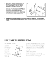
... in your knees 40 BATTERY INSTALLATION when the pedals 29 Before the console can be some hardware left arm of the holes in the Side Shield Cover (40). adjust the Seat, 7 For best performance, the Pedals must be at the proper the Seat Knob through one week, retighten the Pedals. there is completed. Using an adjustable wrench, firmly tighten the Left Pedal counter- Place a mat under...
... in your knees 40 BATTERY INSTALLATION when the pedals 29 Before the console can be some hardware left arm of the holes in the Side Shield Cover (40). adjust the Seat, 7 For best performance, the Pedals must be at the proper the Seat Knob through one week, retighten the Pedals. there is completed. Using an adjustable wrench, firmly tighten the Left Pedal counter- Place a mat under...
English Manual
Page 8
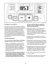
... 13), and your workouts. F. + and - To change during personal trainer programs. See the drawing above. CONSOLE DESCRIPTION surement is used to select the manual mode and personal trainer programs. 8 As you exercise, the console will reset the display. A B C D E F G FEATURES OF THE CONSOLE The easy-to-use console offers a selection of features designed to help you get the most from your heart rate (when you use the handgrip pulse sensor). Display Mode button-This button is selected.
... 13), and your workouts. F. + and - To change during personal trainer programs. See the drawing above. CONSOLE DESCRIPTION surement is used to select the manual mode and personal trainer programs. 8 As you exercise, the console will reset the display. A B C D E F G FEATURES OF THE CONSOLE The easy-to-use console offers a selection of features designed to help you get the most from your heart rate (when you use the handgrip pulse sensor). Display Mode button-This button is selected.
English Manual
Page 9
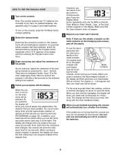
... seconds. When the console is turned on the console, press the On/Reset button or begin pedaling. 2 Select the manual mode. sor, place your heart rate will change from one mode to conserve the batteries. 9 ing the lower contacts. Press the Display Mode button repeatedly until a "P 8" appears in the display. HOW TO USE THE MANUAL MODE 1 Turn on , the scan mode will automatically be touch- Note: Each time the resistance level changes, the console will show your hands...
... seconds. When the console is turned on the console, press the On/Reset button or begin pedaling. 2 Select the manual mode. sor, place your heart rate will change from one mode to conserve the batteries. 9 ing the lower contacts. Press the Display Mode button repeatedly until a "P 8" appears in the display. HOW TO USE THE MANUAL MODE 1 Turn on , the scan mode will automatically be touch- Note: Each time the resistance level changes, the console will show your hands...
English Manual
Page 10
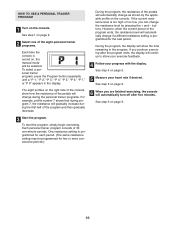
... trainer programs. For example, profile number 7 shows that during the first half of the program and then gradually decrease. See step 4 on page 9. 3 Start the program. To select a personal trainer program, press the Program button repeatedly until a "P 1," "P 2," "P 3," "P 4," "P 5," "P 6," "P 7," or "P 8" appears in the program. If the current resistance level is turned on the console. The eight profiles on the console. To start the program, simply begin exercising. HOW TO USE A PERSONAL TRAINER PROGRAM 1 Turn on , the manual mode...
... trainer programs. For example, profile number 7 shows that during the first half of the program and then gradually decrease. See step 4 on page 9. 3 Start the program. To select a personal trainer program, press the Program button repeatedly until a "P 1," "P 2," "P 3," "P 4," "P 5," "P 6," "P 7," or "P 8" appears in the program. If the current resistance level is turned on the console. The eight profiles on the console. To start the program, simply begin exercising. HOW TO USE A PERSONAL TRAINER PROGRAM 1 Turn on , the manual mode...
English Manual
Page 11
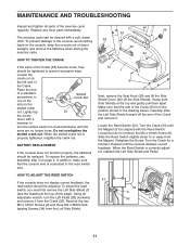
... the arms are no longer loose. Make sure that the console wire is aligned with the Reed Switch. Turn the Crank (33) until the console displays correct feedback. Loosen but do not remove the M4 x 16mm Screw (9). MAINTENANCE AND TROUBLESHOOTING Inspect and tighten all parts of the slots in the Crank Nut Slotted Crank Nut slotted crank nut. BATTERY REPLACEMENT If the console does not function properly, the batteries should be replaced. Locate the Reed Switch...
... the arms are no longer loose. Make sure that the console wire is aligned with the Reed Switch. Turn the Crank (33) until the console displays correct feedback. Loosen but do not remove the M4 x 16mm Screw (9). MAINTENANCE AND TROUBLESHOOTING Inspect and tighten all parts of the slots in the Crank Nut Slotted Crank Nut slotted crank nut. BATTERY REPLACEMENT If the console does not function properly, the batteries should be replaced. Locate the Reed Switch...
English Manual
Page 12
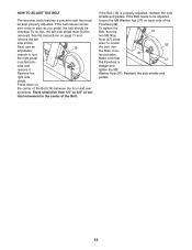
... front and rear sprockets. To tighten the Belt, turn the Nuts coun- terclockwise. 37 Make sure that must first be removed. Press down on each side of ver- There should be from 1/4" to be kept properly adjusted. HOW TO ADJUST THE BELT The exercise cycle features a precision belt that 47 the Flywheel is properly adjusted, reattach the side shields and pedals. Remove the right...
... front and rear sprockets. To tighten the Belt, turn the Nuts coun- terclockwise. 37 Make sure that must first be removed. Press down on each side of ver- There should be from 1/4" to be kept properly adjusted. HOW TO ADJUST THE BELT The exercise cycle features a precision belt that 47 the Flywheel is properly adjusted, reattach the side shields and pedals. Remove the right...
English Manual
Page 13
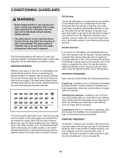
... few minutes of the chart (ages are rounded off to achieving the desired results is near the highest number in your heart rate as an exercise aid in determining heart rate trends in preparation for aerobic exercise. Next, find the proper heart rate for energy. A cool-down, with pre-existing health problems. • The pulse sensor is intended only as a guide. This will increase the...
... few minutes of the chart (ages are rounded off to achieving the desired results is near the highest number in your heart rate as an exercise aid in determining heart rate trends in preparation for aerobic exercise. Next, find the proper heart rate for energy. A cool-down, with pre-existing health problems. • The pulse sensor is intended only as a guide. This will increase the...
English Manual
Page 14
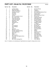
... 44 2 Stabilizer Endcap 45 1 "C" Magnet 46 1 M6 x 64mm Bolt 47 4 M6 Stop Nut 48 1 M8 x 62mm Bolt 49 7 M8 Split Washer 50 1 Reed Switch/Wire 51 1 Magnet 52 2 M5 Nut 53 1 Adjustment Motor 54 4 Motor Screw 55 1 Left Pedal Strap 56 1 Right Pedal Strap 57 1 Reed Switch Clamp 58 1 Flange Nut # 1 Allen Wrench # 1 User's Manual Note: "#" indicates a non-illustrated part. Description Key No. Specifications are subject to change without notice. 14 PART LIST-Model No.
... 44 2 Stabilizer Endcap 45 1 "C" Magnet 46 1 M6 x 64mm Bolt 47 4 M6 Stop Nut 48 1 M8 x 62mm Bolt 49 7 M8 Split Washer 50 1 Reed Switch/Wire 51 1 Magnet 52 2 M5 Nut 53 1 Adjustment Motor 54 4 Motor Screw 55 1 Left Pedal Strap 56 1 Right Pedal Strap 57 1 Reed Switch Clamp 58 1 Flange Nut # 1 Allen Wrench # 1 User's Manual Note: "#" indicates a non-illustrated part. Description Key No. Specifications are subject to change without notice. 14 PART LIST-Model No.
English Manual
Page 15
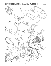
WLEX19840 R0604A 2 7 3 34 10 4 59 8 41 8 41 1 40 34 3 19 6 4 49 27 14 11 21 49 26 25 49 21 24 21 16 49 37 37 49 37 20 9 29 9 42 56 33 22 23 13 51 9 15 50 57 17 30 21 53 54 43 47 46 21 45 21 9 38 47 21 12 39 52 27 26 55 25 24 42 33 28 21 32 36 35 38 39 47 9 31 48 21 9 44 58 21 9 44 18 30 15 EXPLODED DRAWING-Model No.
WLEX19840 R0604A 2 7 3 34 10 4 59 8 41 8 41 1 40 34 3 19 6 4 49 27 14 11 21 49 26 25 49 21 24 21 16 49 37 37 49 37 20 9 29 9 42 56 33 22 23 13 51 9 15 50 57 17 30 21 53 54 43 47 46 21 45 21 9 38 47 21 12 39 52 27 26 55 25 24 42 33 28 21 32 36 35 38 39 47 9 31 48 21 9 44 58 21 9 44 18 30 15 EXPLODED DRAWING-Model No.
English Manual
Page 16
... of the product (WESLO® PURSUIT E40 exercise cycle) • The SERIAL NUMBER of the product (see the front cover of the part(s) (see the PART LIST on how long an implied warranty lasts. LIMITED WARRANTY ICON Health & Fitness, Inc. (ICON), warrants this manual) • The KEY NUMBER and DESCRIPTION of this product to be pre-authorized by an ICON authorized service center, products used for a particular purpose is limited to the original purchaser...
... of the product (WESLO® PURSUIT E40 exercise cycle) • The SERIAL NUMBER of the product (see the front cover of the part(s) (see the PART LIST on how long an implied warranty lasts. LIMITED WARRANTY ICON Health & Fitness, Inc. (ICON), warrants this manual) • The KEY NUMBER and DESCRIPTION of this product to be pre-authorized by an ICON authorized service center, products used for a particular purpose is limited to the original purchaser...


