
English Manual
Page 1
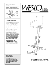
... or damaged parts, we will provide immediate assistance, free of charge to you have questions, or if there are committed to providing complete customer satisfaction. Write the serial number in this manual before using this manual for future reference. Model No. WLST41080 ¨ Serial No. The trained technicians on our customer hot line will guarantee complete satisfaction through direct assistance from...
... or damaged parts, we will provide immediate assistance, free of charge to you have questions, or if there are committed to providing complete customer satisfaction. Write the serial number in this manual before using this manual for future reference. Model No. WLST41080 ¨ Serial No. The trained technicians on our customer hot line will guarantee complete satisfaction through direct assistance from...
English Manual
Page 2
...-free at 1-800-999-3756, Monday through Friday, 6 a.m. The model number is WLST41080. until 6 p.m. The serial number can be found on a decal attached to provide you use the WESLO¨ 450T. Mountain Time (excluding holidays). TABLE OF CONTENTS BEFORE YOU BEGIN 2 IMPORTANT PRECAUTIONS 3 ASSEMBLY 4 HOW TO USE THE STEPPER 6 STORAGE AND TROUBLE-SHOOTING 7 CONDITIONING GUIDELINES 9 PART LIST 10 EXPLODED DRAWING 11 HOW TO ORDER REPLACEMENT PARTS Back Cover LIMITED WARRANTY...
...-free at 1-800-999-3756, Monday through Friday, 6 a.m. The model number is WLST41080. until 6 p.m. The serial number can be found on a decal attached to provide you use the WESLO¨ 450T. Mountain Time (excluding holidays). TABLE OF CONTENTS BEFORE YOU BEGIN 2 IMPORTANT PRECAUTIONS 3 ASSEMBLY 4 HOW TO USE THE STEPPER 6 STORAGE AND TROUBLE-SHOOTING 7 CONDITIONING GUIDELINES 9 PART LIST 10 EXPLODED DRAWING 11 HOW TO ORDER REPLACEMENT PARTS Back Cover LIMITED WARRANTY...
English Manual
Page 3
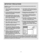
... resistance cylinders, causing serious injury. ! The resistance cylinders may become hot after a period of this product may become caught on the pedals when stepping, or the pedals may result in this or any exercise program, consult your feet on the stepper. Inspect and tighten all instructions in serious injury. • Read user's manual and follow all users of the stepper are adequately informed...
... resistance cylinders, causing serious injury. ! The resistance cylinders may become hot after a period of this product may become caught on the pedals when stepping, or the pedals may result in this or any exercise program, consult your feet on the stepper. Inspect and tighten all instructions in serious injury. • Read user's manual and follow all users of the stepper are adequately informed...
English Manual
Page 4
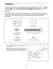
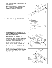
... Console Screw (22)Ð4 M4 x 10mm Screw (28)Ñ8 1. Press a Stabilizer Endcap (13) onto each drawing refers to the key number of the Base (2) with two M10 x 65mm Hex Head Bolts (24), two Washers (25) and two M10 Locknuts (15). 13 8 25 24 15 2 15 25 13 4 The number in parenthesis below to identify the small parts used in assembly. The...
... Console Screw (22)Ð4 M4 x 10mm Screw (28)Ñ8 1. Press a Stabilizer Endcap (13) onto each drawing refers to the key number of the Base (2) with two M10 x 65mm Hex Head Bolts (24), two Washers (25) and two M10 Locknuts (15). 13 8 25 24 15 2 15 25 13 4 The number in parenthesis below to identify the small parts used in assembly. The...
English Manual
Page 5
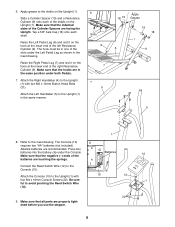
... Right Pedal Leg (7) which has a Magnet (26) attached to attach the Left Pedal Leg (6). 5. Slide the Right Pedal Leg (7) onto the shaft on the Base (2). Tap a 3/4Ó Axle Cap (17) onto the shaft. Repeat this step to it. Attach the Upright with four M4 x 10mm Screws (28). 3 11 6 4. Press a Stabilizer Endcap (13) onto each Pedal Leg (6, 7) with four M10 Locknuts (15). 28 4 6 Apply Grease to the Pedal Leg...
... Right Pedal Leg (7) which has a Magnet (26) attached to attach the Left Pedal Leg (6). 5. Slide the Right Pedal Leg (7) onto the shaft on the Base (2). Tap a 3/4Ó Axle Cap (17) onto the shaft. Repeat this step to it. Attach the Upright with four M4 x 10mm Screws (28). 3 11 6 4. Press a Stabilizer Endcap (13) onto each Pedal Leg (6, 7) with four M10 Locknuts (15). 28 4 6 Apply Grease to the Pedal Leg...
English Manual
Page 6
... of the right Resistance Cylinder (9). The Console (10) 8 requires two ÒAAÓ batteries (not included). Connect the Reed Switch Wire (12) to the Upright (1) in the same manner. 6 Slots 9 7 7 5 18 19 Apply Grease 19 18 1 6 9 21 4 1 8. Apply grease to the Upright (1) with two M6 x 12mm Button Head Bolts (21). Raise the Left Pedal Leg (6) and rest it on the hook at the lower end of...
... of the right Resistance Cylinder (9). The Console (10) 8 requires two ÒAAÓ batteries (not included). Connect the Reed Switch Wire (12) to the Upright (1) in the same manner. 6 Slots 9 7 7 5 18 19 Apply Grease 19 18 1 6 9 21 4 1 8. Apply grease to the Upright (1) with two M6 x 12mm Button Head Bolts (21). Raise the Left Pedal Leg (6) and rest it on the hook at the lower end of...
English Manual
Page 7
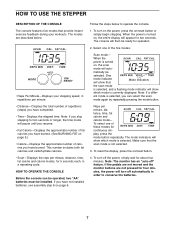
... exercise feedback during your stepping speed, in a repeating cycle. If the pedals are not moved and the monitor buttons are described below to conserve the batteries. 7 The modes are not pressed for operation. 2. When the power is turned on page 6. To turn on the power, press the on /reset button. 4. To reset the display, press the on /reset button or simply begin stepping. Follow the steps below . ¥ Reps Per MinuteÑDisplays your workouts. The console...
... exercise feedback during your stepping speed, in a repeating cycle. If the pedals are not moved and the monitor buttons are described below to conserve the batteries. 7 The modes are not pressed for operation. 2. When the power is turned on page 6. To turn on the power, press the on /reset button. 4. To reset the display, press the on /reset button or simply begin stepping. Follow the steps below . ¥ Reps Per MinuteÑDisplays your workouts. The console...
English Manual
Page 8
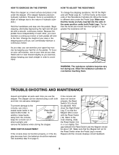
... Reed Switch when the Pedal Leg is level with a smooth, continuous motion. To change the stepping resistance, first lift the Right and Left Pedal Legs (6, 7) off the hooks at the lower ends of direct sunlight, and remove the batteries when storing the stepper. Hold down the Right Pedal Leg (7) so that the Magnet (26) is moved. Move the hooks to avoid injury. TROUBLE-SHOOTING AND MAINTENANCE Inspect and tighten all parts...
... Reed Switch when the Pedal Leg is level with a smooth, continuous motion. To change the stepping resistance, first lift the Right and Left Pedal Legs (6, 7) off the hooks at the lower ends of direct sunlight, and remove the batteries when storing the stepper. Hold down the Right Pedal Leg (7) so that the Magnet (26) is moved. Move the hooks to avoid injury. TROUBLE-SHOOTING AND MAINTENANCE Inspect and tighten all parts...
English Manual
Page 9
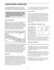
... rapidly when you stop exercising and place two fingers on the lungs to oxygenate the blood. WARNING: Before beginning this or any exercise program, consult your body temperature, heart rate, and circulation in your training zone. (During the first few minutes of exercise does your age. The chart below of your body begin to use stored fat calories for exercise. Take a six-second...
... rapidly when you stop exercising and place two fingers on the lungs to oxygenate the blood. WARNING: Before beginning this or any exercise program, consult your body temperature, heart rate, and circulation in your training zone. (During the first few minutes of exercise does your age. The chart below of your body begin to use stored fat calories for exercise. Take a six-second...
English Manual
Page 10
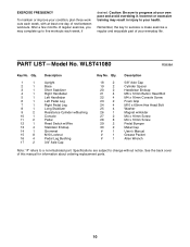
... your health. Remember, the key to five workouts each week, with at your own pace and avoid overdoing it. Qty. 1 1 2 1 3 1 4 1 5 1 6 1 7 1 8 1 9 2 10 1 11 2 12 1 13 4 14 1 15 8 16 4 17 2 Description Upright Base Short Stabilizer Right Handlebar Left Handlebar Left Pedal Leg Right Pedal Leg Long Stabilizer Resistance Cylinder w/Bushing Console Pedal Reed Switch w/Wire Stabilizer Endcap Grommet M10 Locknut Pedal Leg Bushing 3/4Ó Axle Cap Key No. EXERCISE FREQUENCY...
... your health. Remember, the key to five workouts each week, with at your own pace and avoid overdoing it. Qty. 1 1 2 1 3 1 4 1 5 1 6 1 7 1 8 1 9 2 10 1 11 2 12 1 13 4 14 1 15 8 16 4 17 2 Description Upright Base Short Stabilizer Right Handlebar Left Handlebar Left Pedal Leg Right Pedal Leg Long Stabilizer Resistance Cylinder w/Bushing Console Pedal Reed Switch w/Wire Stabilizer Endcap Grommet M10 Locknut Pedal Leg Bushing 3/4Ó Axle Cap Key No. EXERCISE FREQUENCY...
English Manual
Page 11
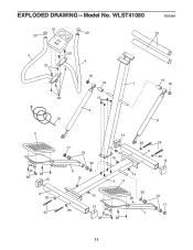
EXPLODED DRAWINGÑModel No. WLST41080 R0998A 10 20 23 20 5 21 21 4 18 19 19 1 18 22 15 9 12 9 11 29 27 28 28 13 8 25 24 17 16 30 6 15 13 14 15 25 3 24 25 13 15 2 11 30 15 16 26 13 25 29 27 28 28 17 7 11
EXPLODED DRAWINGÑModel No. WLST41080 R0998A 10 20 23 20 5 21 21 4 18 19 19 1 18 22 15 9 12 9 11 29 27 28 28 13 8 25 24 17 16 30 6 15 13 14 15 25 3 24 25 13 15 2 11 30 15 16 26 13 25 29 27 28 28 17 7 11
English Manual
Page 12
... do not allow limitations on page 10 of this manual). ¥ The KEY NUMBER and DESCRIPTION of the part(s) (see the front cover of this manual). HOW TO ORDER REPLACEMENT PARTS To order replacement parts, call our Customer Service Department toll-free at one of its authorized service centers. ICON HEALTH & FITNESS, INC., 1500 S. 1000 W., LOGAN, UT 84321-9813 Part No. 149205 R0998A Printed in connection with respect to...
... do not allow limitations on page 10 of this manual). ¥ The KEY NUMBER and DESCRIPTION of the part(s) (see the front cover of this manual). HOW TO ORDER REPLACEMENT PARTS To order replacement parts, call our Customer Service Department toll-free at one of its authorized service centers. ICON HEALTH & FITNESS, INC., 1500 S. 1000 W., LOGAN, UT 84321-9813 Part No. 149205 R0998A Printed in connection with respect to...


