
Uk Manual
Page 6
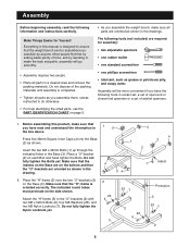
... the "H"-frame (5) over the two "U"-brackets (2) on the side shown. Place a "U"-bracket (2) on the bottom and that the weight bench can be more convenient if you have the following tools (not included) are oriented as grease or petroleum jelly, and soapy water. Assembly Before... beginning assembly, read and understand the information in 1 2 the box above. Press five 38mm Square Inner Caps (4) into the Base (3) as shown in the drawings. The following tools: A socket set, a set of open...
... the "H"-frame (5) over the two "U"-brackets (2) on the side shown. Place a "U"-bracket (2) on the bottom and that the weight bench can be more convenient if you have the following tools (not included) are oriented as grease or petroleum jelly, and soapy water. Assembly Before... beginning assembly, read and understand the information in 1 2 the box above. Press five 38mm Square Inner Caps (4) into the Base (3) as shown in the drawings. The following tools: A socket set, a set of open...
Uk Manual
Page 7
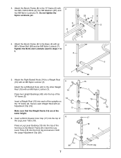
Insert a Weight Rest (15) into the top of the uprights on the Bench Frame (8). Secure each of the front leg on the "H"-frame (5). Press a Leg Lever Bushing (19) into each Weight Rest with an M8 Nylon Locknut (7). Do not tighten the Nylon Locknuts yet. 6 8 4. Make sure that the Weight ... and Locknuts used in steps 1 to the other Weight Rest (15) with 3 two M8 x 52mm Bolts (6), two M8 Washers (23), and two M8 Nylon Locknuts (7). Press two Upright Bushings (48) onto the top of the Leg Lever Tube (18). Attach the Right Barbell Hook (14) to the "H"-frame (5) with an M8...
Insert a Weight Rest (15) into the top of the uprights on the Bench Frame (8). Secure each of the front leg on the "H"-frame (5). Press a Leg Lever Bushing (19) into each Weight Rest with an M8 Nylon Locknut (7). Do not tighten the Nylon Locknuts yet. 6 8 4. Make sure that the Weight ... and Locknuts used in steps 1 to the other Weight Rest (15) with 3 two M8 x 52mm Bolts (6), two M8 Washers (23), and two M8 Nylon Locknuts (7). Press two Upright Bushings (48) onto the top of the Leg Lever Tube (18). Attach the Right Barbell Hook (14) to the "H"-frame (5) with an M8...
Uk Manual
Page 8
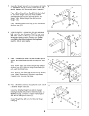
...Tubes (30) into each end of the two Short Pad Tubes (30) and the Long Pad Tube (32). Press a 25mm Round Inner Cap (24) into the holes in the Leg Lever Tube (18) as shown. Slide...44 32 44 18 44 44 Insert the Long Pad Tube (32) into each end of the Weight Tube. Press a 19mm Round Inner Cap (44) into the hole in the Leg Lever (27). Slide two Large Foam... onto the other end of the Leg Lever (27). 4 24 26 7 23 21 4 8. Press a 38mm Square Inner Cap (4) into the indicated end of grease. Press a 25mm Round Inner Cap (24) into each end of 10 a Butterfly Weight Tube (35)....
...Tubes (30) into each end of the two Short Pad Tubes (30) and the Long Pad Tube (32). Press a 25mm Round Inner Cap (24) into the holes in the Leg Lever Tube (18) as shown. Slide...44 32 44 18 44 44 Insert the Long Pad Tube (32) into each end of the Weight Tube. Press a 19mm Round Inner Cap (44) into the hole in the Leg Lever (27). Slide two Large Foam... onto the other end of the Leg Lever (27). 4 24 26 7 23 21 4 8. Press a 38mm Square Inner Cap (4) into the indicated end of grease. Press a 25mm Round Inner Cap (24) into each end of 10 a Butterfly Weight Tube (35)....
Uk Manual
Page 9
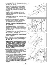
...). Do not tighten the Screws yet. 9 9 Make sure that the button on the Left Butterfly Arm (36) into the end of the tube on the Bench Frame (8). Fasten the Backrest Bracket to insert a Spring Clip (43) into the Bushings. Tighten all four Screws in the drawing. 11. Slide a Small Foam Pad...the lock- 10 ing pin wrapped around the "H"-frame. Wet then end of the Left Butterfly Arm (36). 12. Pin 9 9 11 Round Holes 12 5 8 11 Press a 19mm Round Inner Cap (44) into the centre set of the Backrest, so that is outside the "H"-frame (5). Rotate the Adjustment Tube to one end...
...). Do not tighten the Screws yet. 9 9 Make sure that the button on the Left Butterfly Arm (36) into the end of the tube on the Bench Frame (8). Fasten the Backrest Bracket to insert a Spring Clip (43) into the Bushings. Tighten all four Screws in the drawing. 11. Slide a Small Foam Pad...the lock- 10 ing pin wrapped around the "H"-frame. Wet then end of the Left Butterfly Arm (36). 12. Pin 9 9 11 Round Holes 12 5 8 11 Press a 19mm Round Inner Cap (44) into the centre set of the Backrest, so that is outside the "H"-frame (5). Rotate the Adjustment Tube to one end...