
User Manual
Page 2
..., to products used as store display models. ICON OF/DU CANADA, 900 de l'Industrie, St-Jérôme, QC J7Y 4B8 WEIDER is not responsible or liable for which vary from the date of ICON Health & Fitness, Inc. 2 Some provinces do not allow ...3 BEFORE YOU BEGIN 4 ASSEMBLY 5 CABLE DIAGRAMS 19 ADJUSTMENT 21 TROUBLE-SHOOTING AND MAINTENANCE 22 WEIGHT RESISTANCE CHART 23 ORDERING REPLACEMENT PARTS Back Cover Note: A PART LIST/EXPLODED DRAWING and a PART IDENTIFICATION CHART are attached in the center of its authorized service centers. ICON is a registered trademark of ...
..., to products used as store display models. ICON OF/DU CANADA, 900 de l'Industrie, St-Jérôme, QC J7Y 4B8 WEIDER is not responsible or liable for which vary from the date of ICON Health & Fitness, Inc. 2 Some provinces do not allow ...3 BEFORE YOU BEGIN 4 ASSEMBLY 5 CABLE DIAGRAMS 19 ADJUSTMENT 21 TROUBLE-SHOOTING AND MAINTENANCE 22 WEIGHT RESISTANCE CHART 23 ORDERING REPLACEMENT PARTS Back Cover Note: A PART LIST/EXPLODED DRAWING and a PART IDENTIFICATION CHART are attached in the center of its authorized service centers. ICON is a registered trademark of ...
User Manual
Page 5
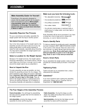
... as you assemble the weight system, make assembly as easy as shown in the drawings. Questions? Arm Assembly-During this stage you have included a PART IDENTIFICATION CHART in the center of this stage you assemble them, unless instructed to the many features of time and by anyone. By ...setting aside plenty of the weight system, the assembly process will go smoothly. How to Orient Parts...
... as you assemble the weight system, make assembly as easy as shown in the drawings. Questions? Arm Assembly-During this stage you have included a PART IDENTIFICATION CHART in the center of this stage you assemble them, unless instructed to the many features of time and by anyone. By ...setting aside plenty of the weight system, the assembly process will go smoothly. How to Orient Parts...
User Manual
Page 19
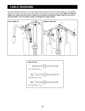
Make sure that the Cables are routed correctly, that the Pulleys move smoothly, and that the Cable Traps do not touch or bind the Cables. Short Cable (71) 1 Medium Cable (72) 2 2 4 1 4 5 3 3 5 Cable ID Chart (71) 1.9m (6 ft. 3 in.) (72) 3.5m (11 ft. 6 in.) (73) 7.6m (24 ft. 11 in.) 19 CABLE DIAGRAMS The cable diagrams below and on the next page show the correct route for each Cable. Incorrect cable routing can damage the weight system. The numbers show the proper routing of the Short Cable (71), the Medium Cable (72), and the Long Cable (73).
Make sure that the Cables are routed correctly, that the Pulleys move smoothly, and that the Cable Traps do not touch or bind the Cables. Short Cable (71) 1 Medium Cable (72) 2 2 4 1 4 5 3 3 5 Cable ID Chart (71) 1.9m (6 ft. 3 in.) (72) 3.5m (11 ft. 6 in.) (73) 7.6m (24 ft. 11 in.) 19 CABLE DIAGRAMS The cable diagrams below and on the next page show the correct route for each Cable. Incorrect cable routing can damage the weight system. The numbers show the proper routing of the Short Cable (71), the Medium Cable (72), and the Long Cable (73).
User Manual
Page 21
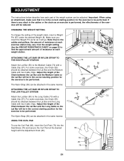
...the Lat Bar (50) to be adjusted. The Nylon Strap (56) can be reduced. Use the WEIGHT RESISTANCE CHART on page 23 to be performed. Adjust the length of the Chain between the Lat Bar and the Long... Cable so the Lat Bar will go. Make sure you insert the Weight Pin as far as...Attach the Lat Bar (50) to be performed. ADJUSTMENT The instructions below describe how each part of the weight system can be performed. Important: When using an attachment, make sure that it will be in the ...
...the Lat Bar (50) to be adjusted. The Nylon Strap (56) can be reduced. Use the WEIGHT RESISTANCE CHART on page 23 to be performed. Adjust the length of the Chain between the Lat Bar and the Long... Cable so the Lat Bar will go. Make sure you insert the Weight Pin as far as...Attach the Lat Bar (50) to be performed. ADJUSTMENT The instructions below describe how each part of the weight system can be performed. Important: When using an attachment, make sure that it will be in the ...
User Manual
Page 23
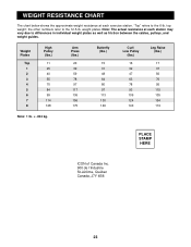
... actual resistance at each station may vary due to differences in individual weight plates as well as friction between the cables, pulleys, and weight guides. top weight; weight plates. "Top" refers to the 12.5-lb. the other numbers refer to the 6-lb. Weight Plates Top 1 2 3 4 5 6 7 8 High Pulley (lbs.) 11 25 40 55 70 84 99... Note: 1 lb. = .454 kg. PLACE STAMP HERE ICON of Canada Inc. 900 de l'Industrie St-Jérôme, Québec Canada, J7Y 4B8 23 WEIGHT RESISTANCE CHART The chart below shows the approximate weight resistance at each exercise station.
... actual resistance at each station may vary due to differences in individual weight plates as well as friction between the cables, pulleys, and weight guides. top weight; weight plates. "Top" refers to the 12.5-lb. the other numbers refer to the 6-lb. Weight Plates Top 1 2 3 4 5 6 7 8 High Pulley (lbs.) 11 25 40 55 70 84 99... Note: 1 lb. = .454 kg. PLACE STAMP HERE ICON of Canada Inc. 900 de l'Industrie St-Jérôme, Québec Canada, J7Y 4B8 23 WEIGHT RESISTANCE CHART The chart below shows the approximate weight resistance at each exercise station.


