

English Manual
Page 1
... the space above for future reference. WESY41080 Serial No. USERÕS MANUAL PATENT PENDING If you have questions, or if there are missing or damaged parts, we are committed to you.
... the space above for future reference. WESY41080 Serial No. USERÕS MANUAL PATENT PENDING If you have questions, or if there are missing or damaged parts, we are committed to you.

English Manual
Page 2
... use the home gym system in the accompanying literature before beginning assembly. If the cables bind while you feel pain or dizziness at any worn parts immediately. 6. Do not use the lat bar. 5. Make sure the cables remain on a level 12. Do not use the VKR station when either weight stack... the lock pin is especially important for persons over the age of 35 or persons with great force. 4. Always disconnect the lat bar from moving parts. 10. When using the home gym system. 8. WARNING: Before beginning this manual. Keep children under the age of 12 and pets away from the ...
... use the home gym system in the accompanying literature before beginning assembly. If the cables bind while you feel pain or dizziness at any worn parts immediately. 6. Do not use the lat bar. 5. Make sure the cables remain on a level 12. Do not use the VKR station when either weight stack... the lock pin is especially important for persons over the age of 35 or persons with great force. 4. Always disconnect the lat bar from moving parts. 10. When using the home gym system. 8. WARNING: Before beginning this manual. Keep children under the age of 12 and pets away from the ...
English Manual
Page 3
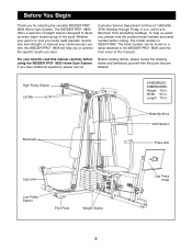
... further, please review the drawing below and familiarize yourself with the parts that are labeled. Customer Service Department toll-free at 1-800-9993756, Monday through Friday, 6 a.m. The model number is to the WEIDER PRO¨ 9835 (see the front cover of the body. Width: 64 in ...Leg Lever Low Pulley Station Foot Plate Weight Stacks 3 Leg Press Plate For your cardiovascular system, the WEIDER PRO¨ 9835 will help us assist you want. The WEIDER PRO¨ 9835 offers a selection of weight stations designed to achieve the specific results you , please note the product...
... further, please review the drawing below and familiarize yourself with the parts that are labeled. Customer Service Department toll-free at 1-800-9993756, Monday through Friday, 6 a.m. The model number is to the WEIDER PRO¨ 9835 (see the front cover of the body. Width: 64 in ...Leg Lever Low Pulley Station Foot Plate Weight Stacks 3 Leg Press Plate For your cardiovascular system, the WEIDER PRO¨ 9835 will help us assist you want. The WEIDER PRO¨ 9835 offers a selection of weight stations designed to achieve the specific results you , please note the product...

English Manual
Page 4
... assembly, we have a socket set, a set of open-end or closed-end wrenches or a set of time, and by deciding to make sure all parts as the skeleton of the Assembly Process Frame Assembly You will save you more convenient if you have broken it has been pre-attached. The...Stages of the equipment. Seat Assembly Completes the seats and backrests that support your new equipment is designed to ensure that the assembly of Parts Tighten all parts are oriented as a unit Arm Assembly Completes the press and butterfly arms that you operate while you are found in individual packages in ...
... assembly, we have a socket set, a set of open-end or closed-end wrenches or a set of time, and by deciding to make sure all parts as the skeleton of the Assembly Process Frame Assembly You will save you more convenient if you have broken it has been pre-attached. The...Stages of the equipment. Seat Assembly Completes the seats and backrests that support your new equipment is designed to ensure that the assembly of Parts Tighten all parts are oriented as a unit Arm Assembly Completes the press and butterfly arms that you operate while you are found in individual packages in ...

English Manual
Page 5
... (40) onto the 1 Carriage Bolts. Do not tighten the Nylon Locknuts yet. Attach the Press Base (13) to the Weight Base. Locate and open the parts bags labeled ÒFRAME ASSEMBLY BAG ONEÓ and ÒFRAME ASSEMBLY BAG TWO.Ó Press a 2Ó Square Outer Cap (58) onto the indicated end...
... (40) onto the 1 Carriage Bolts. Do not tighten the Nylon Locknuts yet. Attach the Press Base (13) to the Weight Base. Locate and open the parts bags labeled ÒFRAME ASSEMBLY BAG ONEÓ and ÒFRAME ASSEMBLY BAG TWO.Ó Press a 2Ó Square Outer Cap (58) onto the indicated end...

English Manual
Page 9
... Frame onto the Press Base (13) so that the Plastic Bushings are aligned with the Bolt and a 3/8Ó Nylon Jamnut (43). Locate and open the parts bag labeled ÒARM ASSEMBLY.Ó Attach the Leg Press Bumper (53) to the Press Base (13) with the Bolt and a 3/8Ó Nylon Locknut (42...
... Frame onto the Press Base (13) so that the Plastic Bushings are aligned with the Bolt and a 3/8Ó Nylon Jamnut (43). Locate and open the parts bag labeled ÒARM ASSEMBLY.Ó Attach the Leg Press Bumper (53) to the Press Base (13) with the Bolt and a 3/8Ó Nylon Locknut (42...

English Manual
Page 11
... a 5/16Ó Nylon Jam Nut 18 (91) onto the Bolt. Slide one end of the Left Arm with the Right Arm (5). 5 Note: The remaining parts from the parts bag labeled ÒARM ASSEMBLYÓ will be able to the CABLE DIAGRAMS on the Right Butterfly Arm (5). 16. Insert a 5/16Ó x 1Ó Bolt...Ó 89Ñ82Ó 85Ñ102Ó 86Ñ86Ó 88Ñ238Ó 91 89 5 95 11 Locate and open the parts bags labeled ÒCABLE ASSEMBLYÓ and ÒPULLEYS.Ó During steps 18 through the bracket on pages 26 and 27 of this section, fully...
... a 5/16Ó Nylon Jam Nut 18 (91) onto the Bolt. Slide one end of the Left Arm with the Right Arm (5). 5 Note: The remaining parts from the parts bag labeled ÒARM ASSEMBLYÓ will be able to the CABLE DIAGRAMS on the Right Butterfly Arm (5). 16. Insert a 5/16Ó x 1Ó Bolt...Ó 89Ñ82Ó 85Ñ102Ó 86Ñ86Ó 88Ñ238Ó 91 89 5 95 11 Locate and open the parts bags labeled ÒCABLE ASSEMBLYÓ and ÒPULLEYS.Ó During steps 18 through the bracket on pages 26 and 27 of this section, fully...

English Manual
Page 12
...; Nylon Jam Nut (91) onto the Bolt, but do not fully tighten it. Make sure the Cable is between the two Jam Nuts for easier part identification. Attach the Pulley and a Cable Trap 21 (80) to the other side of Pulley 20 Plates (31) and 3 1/2Ó Pulleys (82). Attach the Pulley...
...; Nylon Jam Nut (91) onto the Bolt, but do not fully tighten it. Make sure the Cable is between the two Jam Nuts for easier part identification. Attach the Pulley and a Cable Trap 21 (80) to the other side of Pulley 20 Plates (31) and 3 1/2Ó Pulleys (82). Attach the Pulley...

English Manual
Page 17
Note: The 3 1/2Ó Pulley (82) used in this is between the two Jam Nuts for easier part identification. Insert the Bolt into the Front Seat Frame (8). 39 Fully tighten a 5/16Ó Nylon Jam Nut (91) onto the Bolt. Attach the Pulley to ...
Note: The 3 1/2Ó Pulley (82) used in this is between the two Jam Nuts for easier part identification. Insert the Bolt into the Front Seat Frame (8). 39 Fully tighten a 5/16Ó Nylon Jam Nut (91) onto the Bolt. Attach the Pulley to ...

English Manual
Page 20
Locate and open the parts bag labeled ÒSEAT ASSEMBLY.Ó Attach a Small Backrest (97) to the Lat Upright (1) with two 1/4Ó x 1/2Ó Screws (59). Attach the Seat Plate to ...
Locate and open the parts bag labeled ÒSEAT ASSEMBLY.Ó Attach a Small Backrest (97) to the Lat Upright (1) with two 1/4Ó x 1/2Ó Screws (59). Attach the Seat Plate to ...

English Manual
Page 22
... sure that the cables move smoothly, find and correct the problem. IMPORTANT: If the cables are not properly installed, they may be sure that all parts have been properly tightened. Slide the Leg Press Plate (11) onto the end of the adjustment tube (A) on page 26 and 27 of this manual... Arm to remove the slack by tightening the cables. If there is 3 1/2Ó and on the Leg Press Plate (11) and one of the remaining parts will need to 56 the VKR Upright (51) with two 5/16Ó x 3Ó Bolts (92) and two 5/16Ó Nylon Locknuts (40). 57...
... sure that the cables move smoothly, find and correct the problem. IMPORTANT: If the cables are not properly installed, they may be sure that all parts have been properly tightened. Slide the Leg Press Plate (11) onto the end of the adjustment tube (A) on page 26 and 27 of this manual... Arm to remove the slack by tightening the cables. If there is 3 1/2Ó and on the Leg Press Plate (11) and one of the remaining parts will need to 56 the VKR Upright (51) with two 5/16Ó x 3Ó Bolts (92) and two 5/16Ó Nylon Locknuts (40). 57...

English Manual
Page 23
How to Use the Home Gym System The instructions below describe how each part of the Weight Pin is touching the Weights, and turn the bent end downward. IMPORTANT: When attaching the lat bar or handle, make sure that ...
How to Use the Home Gym System The instructions below describe how each part of the Weight Pin is touching the Weights, and turn the bent end downward. IMPORTANT: When attaching the lat bar or handle, make sure that ...

English Manual
Page 25
...85 The Rear Cable (87) can be tightened. install it may have become twisted. Reattach the lower Pulley to be replaced, see ORDERING REPLACEMENT PARTS on the back cover of the Press Cable (88) to slip off the weight stack. Replace any slack is first used on the end ...Pulley, and Large ÒUÓ Bracket (84). Keep the Cable Traps for 82 future use solvents. Trouble-shooting and Maintenance Inspect and tighten all parts each time you feel additional slack while using a damp cloth and mild non-abrasive detergent. Do not use . Re-attach the Pulley and Cable ...
...85 The Rear Cable (87) can be tightened. install it may have become twisted. Reattach the lower Pulley to be replaced, see ORDERING REPLACEMENT PARTS on the back cover of the Press Cable (88) to slip off the weight stack. Replace any slack is first used on the end ...Pulley, and Large ÒUÓ Bracket (84). Keep the Cable Traps for 82 future use solvents. Trouble-shooting and Maintenance Inspect and tighten all parts each time you feel additional slack while using a damp cloth and mild non-abrasive detergent. Do not use . Re-attach the Pulley and Cable ...

English Manual
Page 29
...; Bolt 95 3 5/16Ó x 1Ó Bolt 96 1 Handle 97 1 Small Backrest 98 1 Support Plate # 1 UserÕs Manual # 1 Exercise Poster Note: Ò#Ó indicates a non-illustrated part. Qty. Part List - Model No.
...; Bolt 95 3 5/16Ó x 1Ó Bolt 96 1 Handle 97 1 Small Backrest 98 1 Support Plate # 1 UserÕs Manual # 1 Exercise Poster Note: Ò#Ó indicates a non-illustrated part. Qty. Part List - Model No.

English Manual
Page 33
...Health & Fitness, Inc. You may not apply to state. ICON HEALTH & FITNESS, INC., 1500 S. 1000 W., LOGAN, UT 84321-9813 Part No. 147764 H01818-C R0898A Printed in lieu of any implied warranties of merchantability or fitness for a period of ninety (90) days from state... 1. The KEY NUMBER and DESCRIPTION of the part(s) (see the front cover of the product (WEIDER PRO¨ 9835 Home Gym System). 3. Limited Warranty ICON Health & Fitness, Inc. (ICON), warrants this manual). Ordering Replacement Parts To order replacement parts, simply call our Customer Service Department toll-free...
...Health & Fitness, Inc. You may not apply to state. ICON HEALTH & FITNESS, INC., 1500 S. 1000 W., LOGAN, UT 84321-9813 Part No. 147764 H01818-C R0898A Printed in lieu of any implied warranties of merchantability or fitness for a period of ninety (90) days from state... 1. The KEY NUMBER and DESCRIPTION of the part(s) (see the front cover of the product (WEIDER PRO¨ 9835 Home Gym System). 3. Limited Warranty ICON Health & Fitness, Inc. (ICON), warrants this manual). Ordering Replacement Parts To order replacement parts, simply call our Customer Service Department toll-free...


