
English Manual
Page 2
... WEIGHT RESISTANCE CHART 28 TROUBLE-SHOOTING AND MAINTENANCE 29 CABLE DIAGRAMS 30 ORDERING REPLACEMENT PARTS Back Cover Note: A PART IDENTIFICATION CHART and a PART LIST/EXPLODED DRAWING are attached to the center of charge. Remove the PART IDENTIFICATION CHART and the PART LIST/EXPLODED DRAWING before beginning assembly. This warranty does not apply when the WEIGHT...
... WEIGHT RESISTANCE CHART 28 TROUBLE-SHOOTING AND MAINTENANCE 29 CABLE DIAGRAMS 30 ORDERING REPLACEMENT PARTS Back Cover Note: A PART IDENTIFICATION CHART and a PART LIST/EXPLODED DRAWING are attached to the center of charge. Remove the PART IDENTIFICATION CHART and the PART LIST/EXPLODED DRAWING before beginning assembly. This warranty does not apply when the WEIGHT...
English Manual
Page 3
.... If the cables bind while you feel pain or dizziness at all precautions. 2. The weights will fall with pre-existing health problems. Read all parts often. Read all instructions in place on the rear seat frame (see page 27). 14. Place a mat beneath the home gym system to tip.... 1. It is intended for foot protection. 7. Use the home gym system only on all times. Keep children under 12 and pets away from moving parts. 8. The lock pin must always be replaced every two years. 5. Keep hands and feet away from the home gym system at any commercial, rental...
.... If the cables bind while you feel pain or dizziness at all precautions. 2. The weights will fall with pre-existing health problems. Read all parts often. Read all instructions in place on the rear seat frame (see page 27). 14. Place a mat beneath the home gym system to tip.... 1. It is intended for foot protection. 7. Use the home gym system only on all times. Keep children under 12 and pets away from moving parts. 8. The lock pin must always be replaced every two years. 5. Keep hands and feet away from the home gym system at any commercial, rental...
English Manual
Page 4
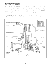
...tone your body, build dramatic muscle size and strength, or improve your benefit, read this manual). The PRO 9735 offers a selection of weight stations designed to the WEIDER® PRO 9735 Home Gym System (see the front cover of the body. Central Time (excluding holidays). High Pulley ...Station Lat Bar ASSEMBLED DIMENSIONS: Height: 79 in. Before reading further, please review the drawing below and familiarize yourself with the parts that are labeled...
...tone your body, build dramatic muscle size and strength, or improve your benefit, read this manual). The PRO 9735 offers a selection of weight stations designed to the WEIDER® PRO 9735 Home Gym System (see the front cover of the body. Central Time (excluding holidays). High Pulley ...Station Lat Bar ASSEMBLED DIMENSIONS: Height: 79 in. Before reading further, please review the drawing below and familiarize yourself with the parts that are labeled...

English Manual
Page 5
...otherwise. Press three 2" Square Outer Caps (58) onto the Weight Base (14) in a cleared area and remove the packing materials; If a part is divided into four stages: 1) frame assembly, 2) press and butterfly arm assembly, 3) cable and pulley assembly and 4) seat and backrest assembly. ...will be needed. Insert a 3/8" x 4" Carriage Bolt (57) up through the Press Base (13). Attach the Press Base (13) to open the parts bags labeled "FRAME ASSEMBLY-METAL" and "FRAME ASSEMBLY-PLASTIC." THE FOLLOWING TOOLS (NOT INCLUDED) ARE REQUIRED FOR ASSEMBLY: • Two (2) adjustable wrenches &#...
...otherwise. Press three 2" Square Outer Caps (58) onto the Weight Base (14) in a cleared area and remove the packing materials; If a part is divided into four stages: 1) frame assembly, 2) press and butterfly arm assembly, 3) cable and pulley assembly and 4) seat and backrest assembly. ...will be needed. Insert a 3/8" x 4" Carriage Bolt (57) up through the Press Base (13). Attach the Press Base (13) to open the parts bags labeled "FRAME ASSEMBLY-METAL" and "FRAME ASSEMBLY-PLASTIC." THE FOLLOWING TOOLS (NOT INCLUDED) ARE REQUIRED FOR ASSEMBLY: • Two (2) adjustable wrenches &#...
English Manual
Page 10
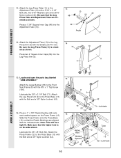
Locate and open the parts bag labeled 15 "ARM ASSEMBLY." Attach the Large Bumper (53) to the Press Base (13) with the #10 x 1" Tap Screw (100). Note: This will be a ...
Locate and open the parts bag labeled 15 "ARM ASSEMBLY." Attach the Large Bumper (53) to the Press Base (13) with the #10 x 1" Tap Screw (100). Note: This will be a ...

English Manual
Page 13
Locate and open the parts bags labeled 23 "CABLE ASSEMBLY" and "PULLEYS." Find the Butterfly Cable (85)-this section, fully unwind the five Cables and identify the Cables by comparing ...
Locate and open the parts bags labeled 23 "CABLE ASSEMBLY" and "PULLEYS." Find the Butterfly Cable (85)-this section, fully unwind the five Cables and identify the Cables by comparing ...

English Manual
Page 14
... Bolt through the bracket on the Leg Press Upright (4) with two holes should be positioned to the inset drawing. Leave just enough room for easier part identification. The Cable Trap must be oriented as shown. Tighten the 3/8" x 2" Bolt (50) and the 3/8" Nylon Locknut (not shown). 26 85 82 50 End with...
... Bolt through the bracket on the Leg Press Upright (4) with two holes should be positioned to the inset drawing. Leave just enough room for easier part identification. The Cable Trap must be oriented as shown. Tighten the 3/8" x 2" Bolt (50) and the 3/8" Nylon Locknut (not shown). 26 85 82 50 End with...

English Manual
Page 15
... is the shortest remaining Cable. Route the High Cable around the 3 1/2" Pulley (82) attached to hold the Cable in this is shown removed for easier part identification. Wrap the High Cable (86) around a 3 1/2" 32 Pulley (82). Locate the remaining pre-assembled pair of the Pulley and that the Cable Trap is...
... is the shortest remaining Cable. Route the High Cable around the 3 1/2" Pulley (82) attached to hold the Cable in this is shown removed for easier part identification. Wrap the High Cable (86) around a 3 1/2" 32 Pulley (82). Locate the remaining pre-assembled pair of the Pulley and that the Cable Trap is...

English Manual
Page 20
...) and a 1/4" Washer (37). Attach the end of threads are showing above the Nylon Locknut, as shown in this step is shown dis-assembled for easier part identification. It should be threaded onto the end of the Cable so only a couple of 46 the Press Cable (88) to hold the Cable in...
...) and a 1/4" Washer (37). Attach the end of threads are showing above the Nylon Locknut, as shown in this step is shown dis-assembled for easier part identification. It should be threaded onto the end of the Cable so only a couple of 46 the Press Cable (88) to hold the Cable in...

English Manual
Page 21
...). Be sure that the Cable is between the Cable Trap (80) and the Pulley, and that the Cable Trap is shown dis-assembled for easier part identification. Wrap the Press Cable (88) around a 3 1/2" Pulley (82). Refer to hold the Cable 88 in the Press Frame (12) with a 3/8" x 3 1/2" Bolt (66), a 3/8" Washer (38...
...). Be sure that the Cable is between the Cable Trap (80) and the Pulley, and that the Cable Trap is shown dis-assembled for easier part identification. Wrap the Press Cable (88) around a 3 1/2" Pulley (82). Refer to hold the Cable 88 in the Press Frame (12) with a 3/8" x 3 1/2" Bolt (66), a 3/8" Washer (38...

English Manual
Page 23
... 4 64 19 37 SEAT ASSEMBLY 23 er 5/16" Nylon Jam Nut (91) onto the Bolt, but do not fully tighten it. Locate and open the parts bag labeled "SEAT ASSEMBLY." Slide a 5/16" Washer (20) onto a 5/16" x 2 3/4" 58 Bolt (55). Slide the end of the Press Cable (88) onto the Bolt. Leave...
... 4 64 19 37 SEAT ASSEMBLY 23 er 5/16" Nylon Jam Nut (91) onto the Bolt, but do not fully tighten it. Locate and open the parts bag labeled "SEAT ASSEMBLY." Slide a 5/16" Washer (20) onto a 5/16" x 2 3/4" 58 Bolt (55). Slide the end of the Press Cable (88) onto the Bolt. Leave...

English Manual
Page 25
... correct the problem. See the CABLE DIAGRAMS on page 29. 25 IMPORTANT: If the cables are not properly installed, they may be sure that all parts have been properly tightened. Remove the decals from the decal sheets (not shown) and apply them to be damaged when heavy weight is any slack... BUTTERFLY AB LEG EXTENSION/CURL ARM PRESS LEG PRESS SERIAL NUMBER DECAL LOW PULLEY/ROW 65. If there is used. If one of the remaining parts will need to remove the slack by tightening the cables. Before using the home gym system, pull each cable a few times to the home gym...
... correct the problem. See the CABLE DIAGRAMS on page 29. 25 IMPORTANT: If the cables are not properly installed, they may be sure that all parts have been properly tightened. Remove the decals from the decal sheets (not shown) and apply them to be damaged when heavy weight is any slack... BUTTERFLY AB LEG EXTENSION/CURL ARM PRESS LEG PRESS SERIAL NUMBER DECAL LOW PULLEY/ROW 65. If there is used. If one of the remaining parts will need to remove the slack by tightening the cables. Before using the home gym system, pull each cable a few times to the home gym...
English Manual
Page 26
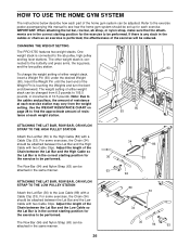
... the exercise will be reduced. HOW TO USE THE HOME GYM SYSTEM The instructions below describe how each part of the home gym system can be attached in the same manner. 26 34 86 33 94 89 33 34 36 94 63 CHANGING THE WEIGHT SETTING The PRO 9735 features two weight stacks.
... the exercise will be reduced. HOW TO USE THE HOME GYM SYSTEM The instructions below describe how each part of the home gym system can be attached in the same manner. 26 34 86 33 94 89 33 34 36 94 63 CHANGING THE WEIGHT SETTING The PRO 9735 features two weight stacks.
English Manual
Page 29
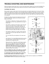
... these 1 cables several ways: 82 80 • See drawing 1. Keep the Cable Traps for future use solvents. Do not overtighten the cables. If any worn parts immediately. Remove the 3/8" Nylon Locknut (42) and the 3/8" x 2" Bolt (50) from the Cable Trap (80), 3 1/2" Pulley (82) and Large "U" Bracket (84). ... there is felt when using the other hole in the Pulley Plates without the Cable Trap. TROUBLE-SHOOTING AND MAINTENANCE Inspect and tighten all parts each time you feel additional slack while using the home gym system, the Rear Cable (87) and the Press Cable (88) can be...
... these 1 cables several ways: 82 80 • See drawing 1. Keep the Cable Traps for future use solvents. Do not overtighten the cables. If any worn parts immediately. Remove the 3/8" Nylon Locknut (42) and the 3/8" x 2" Bolt (50) from the Cable Trap (80), 3 1/2" Pulley (82) and Large "U" Bracket (84). ... there is felt when using the other hole in the Pulley Plates without the Cable Trap. TROUBLE-SHOOTING AND MAINTENANCE Inspect and tighten all parts each time you feel additional slack while using the home gym system, the Rear Cable (87) and the Press Cable (88) can be...
English Manual
Page 34
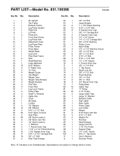
... Low Cable Weight 5/16" Nylon Jam Nut 5/16" x 3" Bolt Weight Pin Row Bar Small Bumper Large Lock Pin 3 1/2" Pro Pulley Support Plate 1/4" x 5/8"" Screw #10 x 1" Tap Screw User's Manual Exercise Poster Note: "#" indicates a non-illustrated part. Specifications are subject to change without notice. Qty. 1 1 2 1 3 1 4 1 5 1 6 1 7 2 8 1 9 1 10 1 11 1 12 1 13 1... Locknut 1" Retainer 1" Round Outer Cap 1 1/8" x 2 1/2" Plastic Bushing 1 3/4" Square Inner Cap 5/16" x 2 1/2" Carriage Bolt 3/8" x 2" Bolt Row Tube Endcap Key No. PART LIST-Model No. 831.159390 R0698A Key No.
... Low Cable Weight 5/16" Nylon Jam Nut 5/16" x 3" Bolt Weight Pin Row Bar Small Bumper Large Lock Pin 3 1/2" Pro Pulley Support Plate 1/4" x 5/8"" Screw #10 x 1" Tap Screw User's Manual Exercise Poster Note: "#" indicates a non-illustrated part. Specifications are subject to change without notice. Qty. 1 1 2 1 3 1 4 1 5 1 6 1 7 2 8 1 9 1 10 1 11 1 12 1 13 1... Locknut 1" Retainer 1" Round Outer Cap 1 1/8" x 2 1/2" Plastic Bushing 1 3/4" Square Inner Cap 5/16" x 2 1/2" Carriage Bolt 3/8" x 2" Bolt Row Tube Endcap Key No. PART LIST-Model No. 831.159390 R0698A Key No.
English Manual
Page 36
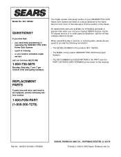
... NUMBER of the product (831.159390). • The NAME of the product (WEIDER® PRO 9735 Home Gym System). • The KEY NUMBER and DESCRIPTION of this manual). See the front cover of the PART (see the PART LIST/EXPLODED DRAWING at the left. When requesting help or service, or ordering...this manual to find that: • you need help assembling or operating the WEIDER® PRO 9735 Home Gym System • a part is missing • or you need to be prepared to the frame. All replacement parts are listed on a decal attached to provide the following tollfree number 1-800-FON...
... NUMBER of the product (831.159390). • The NAME of the product (WEIDER® PRO 9735 Home Gym System). • The KEY NUMBER and DESCRIPTION of this manual). See the front cover of the PART (see the PART LIST/EXPLODED DRAWING at the left. When requesting help or service, or ordering...this manual to find that: • you need help assembling or operating the WEIDER® PRO 9735 Home Gym System • a part is missing • or you need to be prepared to the frame. All replacement parts are listed on a decal attached to provide the following tollfree number 1-800-FON...


