
English Manual
Page 2
... product to you specific legal rights. This warranty gives you . TABLE OF CONTENTS LIMITED WARRANTY 2 IMPORTANT PRECAUTIONS 3 BEFORE YOU BEGIN 4 ASSEMBLY 5 HOW TO USE THE HOME GYM SYSTEM 22 WEIGHT RESISTANCE CHART 24 TROUBLE-SHOOTING AND MAINTENANCE 25 CABLE DIAGRAMS 26 ORDERING REPLACEMENT PARTS Back... Cover Note: A PART IDENTIFICATION CHART and a PART LIST/EXPLODED DRAWING are attached to the center of ICON Health & Fitness, Inc. WEIDER is limited to replacing or repairing, at ICON's option, the product at one of its authorized service centers with respect to any and...
... product to you specific legal rights. This warranty gives you . TABLE OF CONTENTS LIMITED WARRANTY 2 IMPORTANT PRECAUTIONS 3 BEFORE YOU BEGIN 4 ASSEMBLY 5 HOW TO USE THE HOME GYM SYSTEM 22 WEIGHT RESISTANCE CHART 24 TROUBLE-SHOOTING AND MAINTENANCE 25 CABLE DIAGRAMS 26 ORDERING REPLACEMENT PARTS Back... Cover Note: A PART IDENTIFICATION CHART and a PART LIST/EXPLODED DRAWING are attached to the center of ICON Health & Fitness, Inc. WEIDER is limited to replacing or repairing, at ICON's option, the product at one of its authorized service centers with respect to any and...
English Manual
Page 4
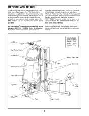
...toll-free at 1-800-9993756, Monday through Friday, 6 a.m. If you for selecting the versatile WEIDER¨ PRO 9648 Home Gym System. Lat Bar High Pulley Station VKR Arms Butterfly Arms ASSEMBLED DIMENSIONS: Height: 76 in . Military Press Arm Backrests Press Arm Leg Lever Low Pulley Station ... specific results you , please note the product model number and serial number before using the WEIDER¨ PRO 9648 Home Gym System. until 6 p.m. The model number is to the WEIDER¨ PRO 9648 (see the front cover of the body. Mountain Time (excluding holidays). For your cardiovascular ...
...toll-free at 1-800-9993756, Monday through Friday, 6 a.m. If you for selecting the versatile WEIDER¨ PRO 9648 Home Gym System. Lat Bar High Pulley Station VKR Arms Butterfly Arms ASSEMBLED DIMENSIONS: Height: 76 in . Military Press Arm Backrests Press Arm Leg Lever Low Pulley Station ... specific results you , please note the product model number and serial number before using the WEIDER¨ PRO 9648 Home Gym System. until 6 p.m. The model number is to the WEIDER¨ PRO 9648 (see the front cover of the body. Mountain Time (excluding holidays). For your cardiovascular ...
English Manual
Page 5
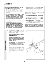
...51) onto the indicated locations on the Stabilizer (5). If a part is broken into the end of the PRO 9648 in a cleared area and remove the packing materials; THE FOLLOWING TOOLS (NOT INCLUDED) ARE REQUIRED FOR ASSEMBLY: ¥ Two (2) adjustable wrenches ¥ One (1) standard screwdriver ¥ One (1) phillips screwdriver ... not in the parts bag, check to see if it has been pre-attached. ¥ As you assemble the PRO 9648 be more convenient if you assemble them, unless instructed to the Stabilizer (5) with two 5/16Ó x 2 3/4Ó Bolts (11), two 5/16Ó Flat Washers (8), and ...
...51) onto the indicated locations on the Stabilizer (5). If a part is broken into the end of the PRO 9648 in a cleared area and remove the packing materials; THE FOLLOWING TOOLS (NOT INCLUDED) ARE REQUIRED FOR ASSEMBLY: ¥ Two (2) adjustable wrenches ¥ One (1) standard screwdriver ¥ One (1) phillips screwdriver ... not in the parts bag, check to see if it has been pre-attached. ¥ As you assemble the PRO 9648 be more convenient if you assemble them, unless instructed to the Stabilizer (5) with two 5/16Ó x 2 3/4Ó Bolts (11), two 5/16Ó Flat Washers (8), and ...

English Manual
Page 6
... (5). Hand-tighten four 5/16Ó Nylon Locknuts (3) onto the Carriage Bolts. The high side of Brackets 56 5 1 1 3. Do not tighten the Nylon Locknuts yet. FRAME ASSEMBLY 4 1 42 6 3 6 Press two 2Ó Square Inner Caps (27) into the Front Upright (42). 2. Attach the Rubber Bumper (91) to the Leg Press Upright (56) with...
... (5). Hand-tighten four 5/16Ó Nylon Locknuts (3) onto the Carriage Bolts. The high side of Brackets 56 5 1 1 3. Do not tighten the Nylon Locknuts yet. FRAME ASSEMBLY 4 1 42 6 3 6 Press two 2Ó Square Inner Caps (27) into the Front Upright (42). 2. Attach the Rubber Bumper (91) to the Leg Press Upright (56) with...

English Manual
Page 7
...Ó x 2 3/4Ó Bolts (11), two 5/16Ó Flat Washers (8), and two 5/16Ó Nylon Locknuts (3). 55 11 49 8 44 3 44 Crossbar 3 56 42 74 FRAME ASSEMBLY 5. Press two 1Ó Round Inner Caps (49) into each stack of Weights (25) until step 8 is complete. 5 56 8 3 6 1 100 11 3 3 1 82 5 Pin Grooves 25 25...
...Ó x 2 3/4Ó Bolts (11), two 5/16Ó Flat Washers (8), and two 5/16Ó Nylon Locknuts (3). 55 11 49 8 44 3 44 Crossbar 3 56 42 74 FRAME ASSEMBLY 5. Press two 1Ó Round Inner Caps (49) into each stack of Weights (25) until step 8 is complete. 5 56 8 3 6 1 100 11 3 3 1 82 5 Pin Grooves 25 25...

English Manual
Page 8
... is sitting in the pin grooves in the Weight Guides are at the top, as shown. 65 Pin 63 62 Lubricate 64 Pin Grooves FRAME ASSEMBLY 25 8.
... is sitting in the pin grooves in the Weight Guides are at the top, as shown. 65 Pin 63 62 Lubricate 64 Pin Grooves FRAME ASSEMBLY 25 8.

English Manual
Page 9
... Bolt and a 3/8Ó Nylon Locknut (21). 9. Attach the upper ends of holes in the Base. Locate and open the parts bag labeled 10 ÒARM ASSEMBLY.Ó Be sure there is a Bushing (98) in each welded spacer on each end of the indicated tube in the Leg Press Arm (96). The... Stabilizer (5) with a 5/16Ó x 6Ó Bolt (60), two 1/2Ó x 3/4Ó Spacers (61), and a 5/16Ó Nylon Locknut (3). 9 61 60 73 3 61 60 3 55 62 FRAME ASSEMBLY ARM ASSEMBLY 10.
... Bolt and a 3/8Ó Nylon Locknut (21). 9. Attach the upper ends of holes in the Base. Locate and open the parts bag labeled 10 ÒARM ASSEMBLY.Ó Be sure there is a Bushing (98) in each welded spacer on each end of the indicated tube in the Leg Press Arm (96). The... Stabilizer (5) with a 5/16Ó x 6Ó Bolt (60), two 1/2Ó x 3/4Ó Spacers (61), and a 5/16Ó Nylon Locknut (3). 9 61 60 73 3 61 60 3 55 62 FRAME ASSEMBLY ARM ASSEMBLY 10.

English Manual
Page 10
... Right Arm with a 3/8Ó x 2 1/2Ó Bolt (86) and a 3/8Ó Nylon Locknut (21). Be sure that the upper end of 12 the Press Arms (46). ARM ASSEMBLY 12. Attach a ÒVÓ-Pulley (50) and a Long Cable Trap (31) to one of the Right Arm is very important for step 14. Tap two...; Round Inner Cap (49) into the lower ends of each Arm with two 5/16Ó x 2 1/2Ó Bolts (22) and two 5/16Ó Nylon Locknuts (3). 22 Assemble the other Press Arm (46) in the same manner. Wet the lower end of the Right and Left Arms (47, 48).
... Right Arm with a 3/8Ó x 2 1/2Ó Bolt (86) and a 3/8Ó Nylon Locknut (21). Be sure that the upper end of 12 the Press Arms (46). ARM ASSEMBLY 12. Attach a ÒVÓ-Pulley (50) and a Long Cable Trap (31) to one of the Right Arm is very important for step 14. Tap two...; Round Inner Cap (49) into the lower ends of each Arm with two 5/16Ó x 2 1/2Ó Bolts (22) and two 5/16Ó Nylon Locknuts (3). 22 Assemble the other Press Arm (46) in the same manner. Wet the lower end of the Right and Left Arms (47, 48).
English Manual
Page 11
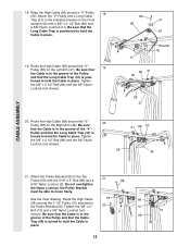
... DIAGRAMS on the indicated side of the Military Press Arm (84). Locate the High Cable (58). Locate and open the parts bags labeled ÒCABLE ASSEMBLYÓ and ÒPULLEYS.Ó 16 During steps 16 through 36, refer to the VKR Upright (74) with the ball is on pages 26Ð...;27 of the Cables. IMPORTANT: While assembling the cables, do not overtighten the bolts and nuts attaching the pulleys. Wrap the High 21 Cable around a 3 1/2Ó Pulley (15). See the inset drawing...
... DIAGRAMS on the indicated side of the Military Press Arm (84). Locate the High Cable (58). Locate and open the parts bags labeled ÒCABLE ASSEMBLYÓ and ÒPULLEYS.Ó 16 During steps 16 through 36, refer to the VKR Upright (74) with the ball is on pages 26Ð...;27 of the Cables. IMPORTANT: While assembling the cables, do not overtighten the bolts and nuts attaching the pulleys. Wrap the High 21 Cable around a 3 1/2Ó Pulley (15). See the inset drawing...
English Manual
Page 12
... (86) and a 3/8Ó Nylon Locknut (21). Tighten the 3/8Ó x 2 1/2Ó Bolt (86) and the 3/8Ó Nylon Locknut (not shown). 58 31 86 50 48 CABLE ASSEMBLY 21. Pulley and that the Cable is turned to hold the Cable in place. Attach the Pulley Bracket (20) to hold the Cable in the...
... (86) and a 3/8Ó Nylon Locknut (21). Tighten the 3/8Ó x 2 1/2Ó Bolt (86) and the 3/8Ó Nylon Locknut (not shown). 58 31 86 50 48 CABLE ASSEMBLY 21. Pulley and that the Cable is turned to hold the Cable in place. Attach the Pulley Bracket (20) to hold the Cable in the...

English Manual
Page 13
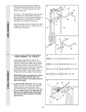
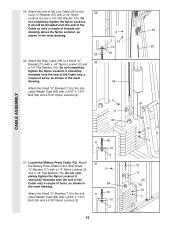
...3 1/2Ó Low Pulley (76), and the 3/8Ó Nylon Locknut (21) are oriented as shown. 13 9 88 7 17 76 21 Note: This may come pre-assembled. Route the High Cable (58) through the Long ÒUÓ-Bracket (57) and the 3 1/2Ó Pulley (15) shown in the groove of the 3 1/2Ó... Be sure that the Cable and Pulley move smoothly. 23. Wrap the High Cable (58) around a 3 1/2Ó Pulley (15). Attach the Pulley to complete the assembly of the Pulley and that the Cable is in the inset drawing. Reattach the 3 1/2Ó Low Pulley (76), with a 3/8Ó x 2Ó Bolt (12) ...
...3 1/2Ó Low Pulley (76), and the 3/8Ó Nylon Locknut (21) are oriented as shown. 13 9 88 7 17 76 21 Note: This may come pre-assembled. Route the High Cable (58) through the Long ÒUÓ-Bracket (57) and the 3 1/2Ó Pulley (15) shown in the groove of the 3 1/2Ó... Be sure that the Cable and Pulley move smoothly. 23. Wrap the High Cable (58) around a 3 1/2Ó Pulley (15). Attach the Pulley to complete the assembly of the Pulley and that the Cable is in the inset drawing. Reattach the 3 1/2Ó Low Pulley (76), with a 3/8Ó x 2Ó Bolt (12) ...

English Manual
Page 14
... 3/8Ó x 3 3/4Ó Bolt (not shown). Be sure that the Cable Trap (66) is turned to the lower hole in the 27 Press Frame (17). CABLE ASSEMBLY 25. Tighten the 3/8Ó Nylon Locknut (21) and the 3/8Ó x 3 3/4Ó Bolt (88). 26 21 42 15 23 15 88 66 42 Inset shows view...
... 3/8Ó x 3 3/4Ó Bolt (not shown). Be sure that the Cable Trap (66) is turned to the lower hole in the 27 Press Frame (17). CABLE ASSEMBLY 25. Tighten the 3/8Ó Nylon Locknut (21) and the 3/8Ó x 3 3/4Ó Bolt (88). 26 21 42 15 23 15 88 66 42 Inset shows view...
English Manual
Page 15
... threaded onto the end of the Cable only a couple of threads are showing above the Nylon Locknut, as shown in 63 the inset drawing. CABLE ASSEMBLY 29. Attach the High Cable (58) to the indi- 71 72 cated Weight Tube (63) with a 1/4Ó Nylon Locknut (2) 3 and a 1/4Ó Flat Washer (10). Do...
... threaded onto the end of the Cable only a couple of threads are showing above the Nylon Locknut, as shown in 63 the inset drawing. CABLE ASSEMBLY 29. Attach the High Cable (58) to the indi- 71 72 cated Weight Tube (63) with a 1/4Ó Nylon Locknut (2) 3 and a 1/4Ó Flat Washer (10). Do...

English Manual
Page 16
... Bracket 21 5 33. Be sure that the Nylon Locknut is turned to hold the Cable in place. 33 15 88 66 9 101 72 21 CABLE ASSEMBLY 16 Wrap the Military Press Cable (72) around a 3 1/2Ó Pulley (15). Be sure that the Cable Trap is on the Stabilizer (5) with a 3/8Ó x 2Ó Bolt...
... Bracket 21 5 33. Be sure that the Nylon Locknut is turned to hold the Cable in place. 33 15 88 66 9 101 72 21 CABLE ASSEMBLY 16 Wrap the Military Press Cable (72) around a 3 1/2Ó Pulley (15). Be sure that the Cable Trap is on the Stabilizer (5) with a 3/8Ó x 2Ó Bolt...

English Manual
Page 17
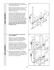
... drawing B. Locate the Leg Press Cable (99). Attach the Pulley to pivot. 15 57 72 21 57 11 8 15 A 66 12 B 101 93 72 CABLE ASSEMBLY 35. The ball on the Cable must be room between the Pulley and the welded rod. 2 10 57 16 15 99 17 99 Welded 2 Rod... Washer (8) onto a 5/16Ó x 2 3/4 Bolt (11). Tighten a 5/16Ó Nylon Jam Nut (93) onto the Bolt. Be sure that the Cable and Pulley move smoothly. assembled.) Route the Military Press Cable (72) through the Pivot Arm (101) from the indicated side. There must be threaded onto the end of the Cable...
... drawing B. Locate the Leg Press Cable (99). Attach the Pulley to pivot. 15 57 72 21 57 11 8 15 A 66 12 B 101 93 72 CABLE ASSEMBLY 35. The ball on the Cable must be room between the Pulley and the welded rod. 2 10 57 16 15 99 17 99 Welded 2 Rod... Washer (8) onto a 5/16Ó x 2 3/4 Bolt (11). Tighten a 5/16Ó Nylon Jam Nut (93) onto the Bolt. Be sure that the Cable and Pulley move smoothly. assembled.) Route the Military Press Cable (72) through the Pivot Arm (101) from the indicated side. There must be threaded onto the end of the Cable...
English Manual
Page 18
...11). Insert the 1/4Ó x 2 1/2Ó Carriage Bolt (92) through the center hole in a Seat Plate (37). Locate and open the parts bag labeled ÒSEAT ASSEMBLY.Ó Insert a 1/4Ó x 2 1/2Ó Carriage Bolt (92) through the indicated hole in the Rear Seat Frame (100) from the indicated side. (Note: The three ... Attach the top of the Bolt. Attach the Press Bracket (94) to pivot. 96 12 11 3 8 99 94 75 15 21 100 93 SEAT ASSEMBLY 37. Insert the Bolt through the lowest hole in the Leg Press Upright (56). There must be room between the two Jam Nuts for cable...
...11). Insert the 1/4Ó x 2 1/2Ó Carriage Bolt (92) through the center hole in a Seat Plate (37). Locate and open the parts bag labeled ÒSEAT ASSEMBLY.Ó Insert a 1/4Ó x 2 1/2Ó Carriage Bolt (92) through the indicated hole in the Rear Seat Frame (100) from the indicated side. (Note: The three ... Attach the top of the Bolt. Attach the Press Bracket (94) to pivot. 96 12 11 3 8 99 94 75 15 21 100 93 SEAT ASSEMBLY 37. Insert the Bolt through the lowest hole in the Leg Press Upright (56). There must be room between the two Jam Nuts for cable...

English Manual
Page 19
... Cap (32) into the Front Seat Frame (36). Insert the 1/4Ó x 2Ó Carriage Bolt (38) through the center hole in the Front Upright (42). SEAT ASSEMBLY 39.
... Cap (32) into the Front Seat Frame (36). Insert the 1/4Ó x 2Ó Carriage Bolt (38) through the center hole in the Front Upright (42). SEAT ASSEMBLY 39.

English Manual
Page 20
... Pad (30) onto each end of the Pad Tube. 29 30 30 34 28 34 44. Locate and open the parts bag labeled ÒVKR ASSEMBLY.Ó Press 1 1/2Ó Square Inner Caps (32) into 43 each Pad Tube (28). Press two 3/4Ó Round Inner Caps (34) into the ends of the... a VKR Armrest (78) to the Left VKR Arm (79) in the same manner. 45 78 10 74 80 81 3 43 10 79 78 77 VKR ASSEMBLY 20 Insert the other Pad Tube (28) into the Seat Frame (36). SEAT...
... Pad (30) onto each end of the Pad Tube. 29 30 30 34 28 34 44. Locate and open the parts bag labeled ÒVKR ASSEMBLY.Ó Press 1 1/2Ó Square Inner Caps (32) into 43 each Pad Tube (28). Press two 3/4Ó Round Inner Caps (34) into the ends of the... a VKR Armrest (78) to the Left VKR Arm (79) in the same manner. 45 78 10 74 80 81 3 43 10 79 78 77 VKR ASSEMBLY 20 Insert the other Pad Tube (28) into the Seat Frame (36). SEAT...

English Manual
Page 25
If the cables have been assembled correctly. Be sure that the four cables and the cable traps have not been correctly routed, the home gym system will not come off the ...
If the cables have been assembled correctly. Be sure that the four cables and the cable traps have not been correctly routed, the home gym system will not come off the ...


