
English Manual
Page 2
TABLE OF CONTENTS IMPORTANT PRECAUTIONS 3 BEFORE YOU BEGIN 4 PART IDENTIFICATION CHART 5 ASSEMBLY 7 ADJUSTMENTS 28 WEIGHT RESISTANCE CHART 31 CABLE DIAGRAM 32 MAINTENANCE 34 EXERCISE GUIDELINES 35 PART LIST 39 EXPLODED DRAWING 41 ORDERING REPLACEMENT PARTS Back Cover 90 DAY FULL WARRANTY Back Cover 2
TABLE OF CONTENTS IMPORTANT PRECAUTIONS 3 BEFORE YOU BEGIN 4 PART IDENTIFICATION CHART 5 ASSEMBLY 7 ADJUSTMENTS 28 WEIGHT RESISTANCE CHART 31 CABLE DIAGRAM 32 MAINTENANCE 34 EXERCISE GUIDELINES 35 PART LIST 39 EXPLODED DRAWING 41 ORDERING REPLACEMENT PARTS Back Cover 90 DAY FULL WARRANTY Back Cover 2
English Manual
Page 3
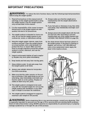
... from moving parts. 7. Place the weight system on the pulleys. Keep children under 12 and pets away from the weight system at all cables at all precautions. 3. Always wear athletic shoes for personal injury or property damage sustained by or through the use only. Replace all times.... 8. Replace any time while exercising, stop immediately and make sure that the cable is intended for persons over the age of the weight system are exercising, stop immediately and begin cooling down. 14. The weight ...
... from moving parts. 7. Place the weight system on the pulleys. Keep children under 12 and pets away from the weight system at all cables at all precautions. 3. Always wear athletic shoes for personal injury or property damage sustained by or through the use only. Replace all times.... 8. Replace any time while exercising, stop immediately and make sure that the cable is intended for persons over the age of the weight system are exercising, stop immediately and begin cooling down. 14. The weight ...
English Manual
Page 7
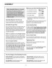
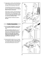
Set Aside Enough Time How to Identify Parts Due to the many features of the weight system, the assembly process will attach the cables and pulleys that connect the arms to the weights. Place all parts of its weight and size, the weight system should be more time... small parts may want to easily identify parts during each assembly step. If a part is not in a cleared area and remove the packing materials. Cable Assembly-During this stage you have questions after reading these assembly instructions, please call 1-800-4-MY-HOME® (1-800-469-4663). You may have the...
Set Aside Enough Time How to Identify Parts Due to the many features of the weight system, the assembly process will attach the cables and pulleys that connect the arms to the weights. Place all parts of its weight and size, the weight system should be more time... small parts may want to easily identify parts during each assembly step. If a part is not in a cleared area and remove the packing materials. Cable Assembly-During this stage you have questions after reading these assembly instructions, please call 1-800-4-MY-HOME® (1-800-469-4663). You may have the...
English Manual
Page 16
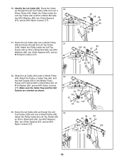
... Left and Right Press Arms (15, 16) to pivot freely. 90 Grease 50 78 28 15 93 79 Grease Flat Edge 26. 24. See the CABLE DIAGRAMS on page 32 and 33 to an M10 x 110mm Bolt (93) and a 90mm Spacer (59). Make sure the flat edge of the... Cable is against the Left Butterfly Bracket. Attach the "V"-pulley, a Long Cable Trap (57), an M10 Washer (80), and two Guards (54) to an M10 x 110mm Bolt (93) and a 90mm Spacer (59...
... Left and Right Press Arms (15, 16) to pivot freely. 90 Grease 50 78 28 15 93 79 Grease Flat Edge 26. 24. See the CABLE DIAGRAMS on page 32 and 33 to an M10 x 110mm Bolt (93) and a 90mm Spacer (59). Make sure the flat edge of the... Cable is against the Left Butterfly Bracket. Attach the "V"-pulley, a Long Cable Trap (57), an M10 Washer (80), and two Guards (54) to an M10 x 110mm Bolt (93) and a 90mm Spacer (59...

English Manual
Page 17
... (2) with an M10 x 63mm Bolt (79) and an M10 Nylon Locknut (77). 79 54 57 50 47 80 54 2 77 29. Attach the "V"-pulley, a Long Cable Trap (57), an M10 Washer (80), and two Guards (54) to the Right Butterfly Bracket (29) with an M10 x 50mm Bolt (97) and an M10... Nylon Locknut (77). 27. Wrap the Butterfly Cable (50) under a 90mm 27 Pulley (48). Make sure the Half Guards are oriented as shown. 50 77 48 97 55 55 61 28.
... (2) with an M10 x 63mm Bolt (79) and an M10 Nylon Locknut (77). 79 54 57 50 47 80 54 2 77 29. Attach the "V"-pulley, a Long Cable Trap (57), an M10 Washer (80), and two Guards (54) to the Right Butterfly Bracket (29) with an M10 x 50mm Bolt (97) and an M10... Nylon Locknut (77). 27. Wrap the Butterfly Cable (50) under a 90mm 27 Pulley (48). Make sure the Half Guards are oriented as shown. 50 77 48 97 55 55 61 28.
English Manual
Page 18
...two M10 Washers (80), two 19mm Spacers (67), and an M10 Nylon Locknut (77). 31. Make sure the Cable Trap and the Half Guards are oriented as shown. 49 55 77 48 97 56 80 127 55 33. Attach ... an M10 x 50mm Bolt (97), an M10 Washer (80), and an M10 Nylon Locknut (77). Route the Lat Cable (49) up through the Left Top Frame (126). 30. Attach the Pulley inside the Left Top Frame with an M10... 48 84 80 67 77 67 80 126 48 84 67 80 80 77 67 49 32. Attach the Pulley, a Cable Trap (56), and two Half Guards (55) to the Military Press Frame (127) with an M10 x 82mm Bolt ...
...two M10 Washers (80), two 19mm Spacers (67), and an M10 Nylon Locknut (77). 31. Make sure the Cable Trap and the Half Guards are oriented as shown. 49 55 77 48 97 56 80 127 55 33. Attach ... an M10 x 50mm Bolt (97), an M10 Washer (80), and an M10 Nylon Locknut (77). Route the Lat Cable (49) up through the Left Top Frame (126). 30. Attach the Pulley inside the Left Top Frame with an M10... 48 84 80 67 77 67 80 126 48 84 67 80 80 77 67 49 32. Attach the Pulley, a Cable Trap (56), and two Half Guards (55) to the Military Press Frame (127) with an M10 x 82mm Bolt ...

English Manual
Page 19
...) over a 90mm Pulley 37 (48). Wrap the Lat Cable (49) under a 90mm Pulley 34 (48). Make sure the Cable Trap and Half Guards are oriented as shown. 35. Make sure the Cable Trap and Half Guards are oriented as shown. 37. Attach the Pulley, a Cable Trap (56), and 36 two Half Guards (55) at... 19 Attach the Pulley to the Right Top Frame (4) with an M10 x 50mm Bolt (97) and an M10 Nylon Locknut (77). Attach the Pulley and a Cable Trap (56) to the Left Top Frame 35 (126) wtih an M10 x 45mm Bolt (86) and an M10 Nylon Locknut (77). 49 48 56 77...
...) over a 90mm Pulley 37 (48). Wrap the Lat Cable (49) under a 90mm Pulley 34 (48). Make sure the Cable Trap and Half Guards are oriented as shown. 35. Make sure the Cable Trap and Half Guards are oriented as shown. 37. Attach the Pulley, a Cable Trap (56), and 36 two Half Guards (55) at... 19 Attach the Pulley to the Right Top Frame (4) with an M10 x 50mm Bolt (97) and an M10 Nylon Locknut (77). Attach the Pulley and a Cable Trap (56) to the Left Top Frame 35 (126) wtih an M10 x 45mm Bolt (86) and an M10 Nylon Locknut (77). 49 48 56 77...

English Manual
Page 20
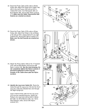
...) over a 90mm Pulley (48). Make sure the flat edge of the Weight Tube (20). Thread the Lat Cable (49) into the Weight Tube (20) two turns. Identify the Press Cable (133). Attach the Pulley to the Left Frame (122) with an M10 x 110mm Bolt (93), two Guards (54), two M10 Washers (80... 54 93 80 48 56 54 Tighten the M12 Nut (112) against the Left Frame. 122 84 77 80 133 41. Attach the Pulley and a Cable Trap (56) to the Leg Press Frame (123) with an M10 x 82mm Bolt (84), an M10 Washer (80), and an M10 Nylon Locknut (77). Make...
...) over a 90mm Pulley (48). Make sure the flat edge of the Weight Tube (20). Thread the Lat Cable (49) into the Weight Tube (20) two turns. Identify the Press Cable (133). Attach the Pulley to the Left Frame (122) with an M10 x 110mm Bolt (93), two Guards (54), two M10 Washers (80... 54 93 80 48 56 54 Tighten the M12 Nut (112) against the Left Frame. 122 84 77 80 133 41. Attach the Pulley and a Cable Trap (56) to the Leg Press Frame (123) with an M10 x 82mm Bolt (84), an M10 Washer (80), and an M10 Nylon Locknut (77). Make...
English Manual
Page 21
...(80), and an M10 Nylon Locknut (77). it should be tightened so that only two threads of the Cable show past the Nylon Locknut. 44 151 78 119 78 151 103 133 133 45. Attach the Pulley to...Spacers (109), and an M10 Nylon Locknut (77). 85 80 109 51 109 10 80 77 21 Route the Press Cable (133) under the indicated bar, and through the Leg Lever (12) and the Front 12 48 Bar 2 Leg ... Insert a 90mm Pulley (48) into the Leg Lever (12) from the indicated direction. Route the Press Cable (133) under a 90mm 42 Pulley (48). Make sure the Half Guards are oriented as shown. 55 77 48 ...
...(80), and an M10 Nylon Locknut (77). it should be tightened so that only two threads of the Cable show past the Nylon Locknut. 44 151 78 119 78 151 103 133 133 45. Attach the Pulley to...Spacers (109), and an M10 Nylon Locknut (77). 85 80 109 51 109 10 80 77 21 Route the Press Cable (133) under the indicated bar, and through the Leg Lever (12) and the Front 12 48 Bar 2 Leg ... Insert a 90mm Pulley (48) into the Leg Lever (12) from the indicated direction. Route the Press Cable (133) under a 90mm 42 Pulley (48). Make sure the Half Guards are oriented as shown. 55 77 48 ...
English Manual
Page 22
... Half Guards are oriented as shown. 55 51 97 Bar 48 55 77 48. Attach the Pulley, a Cable Trap (56), and two Half Guards (55) to the Front Leg with an M10 x 50mm Bolt (...109 80 77 47. Make sure the Half Guards are oriented as shown. 49. Then, wrap 47 the Cable under a 90mm Pulley (48). Attach the Pulley to the Right Base with an M10 x 50mm Bolt ...46 Pulley to the second hole from the indicated direction. Wrap the Leg Lever Cable (51) over a 90mm 48 Pulley (48). Route the Leg Lever Cable (51) under the indicated bars on the Right Base (1). Insert a 90mm ...
... Half Guards are oriented as shown. 55 51 97 Bar 48 55 77 48. Attach the Pulley, a Cable Trap (56), and two Half Guards (55) to the Front Leg with an M10 x 50mm Bolt (...109 80 77 47. Make sure the Half Guards are oriented as shown. 49. Then, wrap 47 the Cable under a 90mm Pulley (48). Attach the Pulley to the Right Base with an M10 x 50mm Bolt ...46 Pulley to the second hole from the indicated direction. Wrap the Leg Lever Cable (51) over a 90mm 48 Pulley (48). Route the Leg Lever Cable (51) under the indicated bars on the Right Base (1). Insert a 90mm ...

English Manual
Page 23
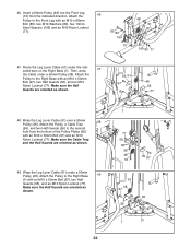
... an M10 x 120mm Bolt (115), two Guards (54), an M10 51 115 48 Washer (80), and an M10 Nylon Locknut (77). Wrap the Leg Lever Cable (51) under a 90mm Pulley (48). Attach the Pulley to the Right Upright (2) with an M10 x 50mm Bolt (97), two Half Guards (55), and an M10... -bracket (61) with an M10 x 50mm Bolt (97), two Half Guards (55), an M10 Washer (80), and an M10 Nylon Locknut (77). Make sure the Cable Trap is oriented as shown. 97 55 51 48 1 55 77 97 55 51 61 77 55 48 52. Make sure the Half Guards are...
... an M10 x 120mm Bolt (115), two Guards (54), an M10 51 115 48 Washer (80), and an M10 Nylon Locknut (77). Wrap the Leg Lever Cable (51) under a 90mm Pulley (48). Attach the Pulley to the Right Upright (2) with an M10 x 50mm Bolt (97), two Half Guards (55), and an M10... -bracket (61) with an M10 x 50mm Bolt (97), two Half Guards (55), an M10 Washer (80), and an M10 Nylon Locknut (77). Make sure the Cable Trap is oriented as shown. 97 55 51 48 1 55 77 97 55 51 61 77 55 48 52. Make sure the Half Guards are...
English Manual
Page 24
...M6 x 16mm Screws (88), an M6 x 32mm Screw (89), and an M6 Washer (114). Wrap the Leg Lever Cable (51) under a 90mm Pulley (48). 54. Attach the Pulley to the Right Backrest Frame (7) with an M10 x ...68mm Bolt (85), two Half Guards (55), an M10 Washer (80), a Long Cable Trap (57), and an M10 Nylon Locknut (77). Insert the Right Backrest Frame (7) into the Right Upright (2) and ...51 77 2 88 53 7 114 89 Remove the indicated M10 Nylon Locknut (77). 56 Attach the Leg Lever Cable (51) to the Left Press Arm (15) with the M10 x 120mm Bolt (115), an M10 Washer (80...
...M6 x 16mm Screws (88), an M6 x 32mm Screw (89), and an M6 Washer (114). Wrap the Leg Lever Cable (51) under a 90mm Pulley (48). 54. Attach the Pulley to the Right Backrest Frame (7) with an M10 x ...68mm Bolt (85), two Half Guards (55), an M10 Washer (80), a Long Cable Trap (57), and an M10 Nylon Locknut (77). Insert the Right Backrest Frame (7) into the Right Upright (2) and ...51 77 2 88 53 7 114 89 Remove the indicated M10 Nylon Locknut (77). 56 Attach the Leg Lever Cable (51) to the Left Press Arm (15) with the M10 x 120mm Bolt (115), an M10 Washer (80...

English Manual
Page 25
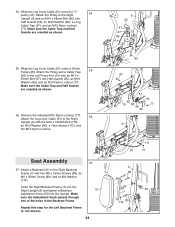
... (129) to the Left Seat 59 Frame (125) with two M6 x 60mm Button Screws (91) and two M6 Washers (114). Note: Lift the Leg Lever Cable (51) when inserting a Pad Tube through the indicated hole in the Right Seat Frame. 59.
... (129) to the Left Seat 59 Frame (125) with two M6 x 60mm Button Screws (91) and two M6 Washers (114). Note: Lift the Leg Lever Cable (51) when inserting a Pad Tube through the indicated hole in the Right Seat Frame. 59.
English Manual
Page 27
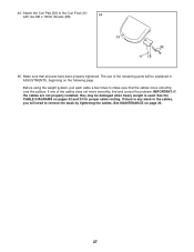
... that all parts have been properly tightened. If one of the remaining parts will need to remove the slack by tightening the cables. Before using the weight system, pull each cable a few times to the Curl Post (11) 64 with two M6 x 16mm Screws (88). 33 88 11 65. If there is... used. IMPORTANT: If the cables are not properly installed, they may be explained in the cables, you will be damaged when heavy weight is any slack in ADJUSTMENTS, beginning on the following page. 64. See the...
... that all parts have been properly tightened. If one of the remaining parts will need to remove the slack by tightening the cables. Before using the weight system, pull each cable a few times to the Curl Post (11) 64 with two M6 x 16mm Screws (88). 33 88 11 65. If there is... used. IMPORTANT: If the cables are not properly installed, they may be explained in the cables, you will be damaged when heavy weight is any slack in ADJUSTMENTS, beginning on the following page. 64. See the...
English Manual
Page 28
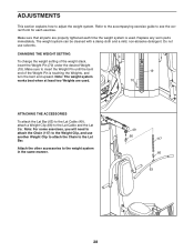
... To change the weight setting of the Weight Pin is used . 19 70 ATTACHING THE ACCESSORIES To attach the Lat Bar (63) to the Lat Cable (49), attach a Weight Clip (66) to adjust the weight system. Make sure to insert the Weight Pin until the bent end of the weight stack... form for each time the weight system is touching the Weights, and turn the bent end upward. ADJUSTMENTS This section explains how to the Lat Cable and the Lat Bar. Note: The weight system works best when at least two Weights are properly tightened each exercise.
... To change the weight setting of the Weight Pin is used . 19 70 ATTACHING THE ACCESSORIES To attach the Lat Bar (63) to the Lat Cable (49), attach a Weight Clip (66) to adjust the weight system. Make sure to insert the Weight Pin until the bent end of the weight stack... form for each time the weight system is touching the Weights, and turn the bent end upward. ADJUSTMENTS This section explains how to the Lat Cable and the Lat Bar. Note: The weight system works best when at least two Weights are properly tightened each exercise.
English Manual
Page 31
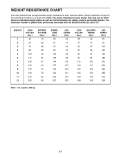
... chart below shows the approximate weight resistance at each station may vary due to differences in individual weight plates as well as friction between the cables, pulleys, and weight guides.
... chart below shows the approximate weight resistance at each station may vary due to differences in individual weight plates as well as friction between the cables, pulleys, and weight guides.
English Manual
Page 32
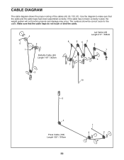
Make sure that the cable and the cable traps have been assembled correctly. If the cable has not been correctly routed, the weight system will not function properly and damage may occur. Use the diagram to make sure that the cable traps do not touch or bind the cable. 4 5 1 2 Butterfly Cable (50) Length 119" / 302cm 3 Lat Cable (49) Length 211" / 536cm 8 6 54 2 1 9 3 7 10 5 4 Press Cable (133) Length 125" / 318cm 32 1 3 2 The numbers show the correct route for the cable. CABLE DIAGRAM The cable diagram shows the proper routing of the cables (49, 50, 133, 51).
Make sure that the cable and the cable traps have been assembled correctly. If the cable has not been correctly routed, the weight system will not function properly and damage may occur. Use the diagram to make sure that the cable traps do not touch or bind the cable. 4 5 1 2 Butterfly Cable (50) Length 119" / 302cm 3 Lat Cable (49) Length 211" / 536cm 8 6 54 2 1 9 3 7 10 5 4 Press Cable (133) Length 125" / 318cm 32 1 3 2 The numbers show the correct route for the cable. CABLE DIAGRAM The cable diagram shows the proper routing of the cables (49, 50, 133, 51).

English Manual
Page 33
4 Leg Lever Cable (51) Length 265" / 672cm 7 8 5 6 9 10 3 12 11 33
4 Leg Lever Cable (51) Length 265" / 672cm 7 8 5 6 9 10 3 12 11 33
English Manual
Page 34
...damp cloth and a mild, non-abrasive detergent. Make sure that the Cable Trap is first used . Reattach the Pulley, Cable Trap, and Half Guards to the next closer hole to hold the cable in the cables before resistance is used . If a cable tends to be replaced, see the part ordering information on 2 the ... Pulley (48), the two Half Guards (55), and the two Pulley Plates (60). Replace any worn parts immediately. If the cables need to slip off the weight stack. Remove the cable and re-install it is oriented to the center of the weight stack. Slack can be removed from these...
...damp cloth and a mild, non-abrasive detergent. Make sure that the Cable Trap is first used . Reattach the Pulley, Cable Trap, and Half Guards to the next closer hole to hold the cable in the cables before resistance is used . If a cable tends to be replaced, see the part ordering information on 2 the ... Pulley (48), the two Half Guards (55), and the two Pulley Plates (60). Replace any worn parts immediately. If the cables need to slip off the weight stack. Remove the cable and re-install it is oriented to the center of the weight stack. Slack can be removed from these...
English Manual
Page 39
... Cap 43 2 Butterfly Arm Cap 44 2 Bolt Cap 45 4 Butterfly Arm Bushing 46 8 Bracket Bushing 47 3 "V"-pulley 48 23 90mm Pulley 49 1 Lat Cable 50 1 Butterfly Cable 51 1 Leg Lever Cable 52 1 Seat Adjustment Knob 53 3 Backrest Adjustment Knob 54 8 Guard 55 28 56 9 57 3 58 1 59 2 60 2 61 1 62 1 63 1 64 2 65... 89 3 90 2 91 4 92 2 93 3 94 1 95 1 96 1 97 12 98 1 99 8 100 22 101 2 102 14 103 26 104 8 105 2 106 6 Half Guard Cable Trap Long Cable Trap Curl Adjustment Knob 90mm Spacer Pulley Plate Double "U"-bracket Ankle Strap Lat Bar Hand Grip Handle Weight Clip 19mm Spacer 25mm Bushing 57mm...
... Cap 43 2 Butterfly Arm Cap 44 2 Bolt Cap 45 4 Butterfly Arm Bushing 46 8 Bracket Bushing 47 3 "V"-pulley 48 23 90mm Pulley 49 1 Lat Cable 50 1 Butterfly Cable 51 1 Leg Lever Cable 52 1 Seat Adjustment Knob 53 3 Backrest Adjustment Knob 54 8 Guard 55 28 56 9 57 3 58 1 59 2 60 2 61 1 62 1 63 1 64 2 65... 89 3 90 2 91 4 92 2 93 3 94 1 95 1 96 1 97 12 98 1 99 8 100 22 101 2 102 14 103 26 104 8 105 2 106 6 Half Guard Cable Trap Long Cable Trap Curl Adjustment Knob 90mm Spacer Pulley Plate Double "U"-bracket Ankle Strap Lat Bar Hand Grip Handle Weight Clip 19mm Spacer 25mm Bushing 57mm...


