
English Manual
Page 18
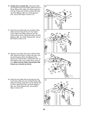
...) over a 90mm Pulley 31 (48) and down through the Left 33 Top Frame (126) and over a 90mm Pulley (48). Route the Lat Cable (49) up through the Left Top Frame (126) and over a 90mm Pulley (48). Attach the Pulley inside the Left Top Frame with an M10 x 82mm ...), and an M10 Nylon Locknut (77). 48 84 49 80 67 80 126 77 67 18 Identify the Lat Cable (49). Wrap the Lat Cable (49) under a 90mm Pulley 32 (48). Route the Cable 30 up through the Left Top Frame (126). Attach the Pulley inside the Left Top Frame with an M10 x 82mm...
...) over a 90mm Pulley 31 (48) and down through the Left 33 Top Frame (126) and over a 90mm Pulley (48). Route the Lat Cable (49) up through the Left Top Frame (126) and over a 90mm Pulley (48). Attach the Pulley inside the Left Top Frame with an M10 x 82mm ...), and an M10 Nylon Locknut (77). 48 84 49 80 67 80 126 77 67 18 Identify the Lat Cable (49). Wrap the Lat Cable (49) under a 90mm Pulley 32 (48). Route the Cable 30 up through the Left Top Frame (126). Attach the Pulley inside the Left Top Frame with an M10 x 82mm...
English Manual
Page 21
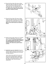
...) with an M10 x 50mm Bolt (97), two Half Guards (55), and an M10 Nylon Locknut (77). Route the Press Cable (133) under a 90mm 42 Pulley (48). it should be tightened so that only two threads of the Cable show past the Nylon Locknut. 44 151 78 119 78 151 103 133 133 45.... Route the 45 Cable through the Leg Lever (12) and the Front 12 48 Bar 2 Leg (10), under the indicated bar...
...) with an M10 x 50mm Bolt (97), two Half Guards (55), and an M10 Nylon Locknut (77). Route the Press Cable (133) under a 90mm 42 Pulley (48). it should be tightened so that only two threads of the Cable show past the Nylon Locknut. 44 151 78 119 78 151 103 133 133 45.... Route the 45 Cable through the Leg Lever (12) and the Front 12 48 Bar 2 Leg (10), under the indicated bar...
English Manual
Page 22
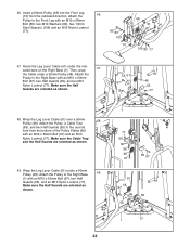
... a 90mm Pulley (48). Make sure the Cable Trap and the Half Guards are oriented as shown. 55 51 97 Bar 48 ... 97 51 48 97 55 55 1 77 Wrap the Leg Lever Cable (51) under a 90mm Pulley (48). Wrap the Leg Lever Cable (51) over a 90mm 48 Pulley (48). Route the Leg Lever Cable (51) under the indicated bars on the Right Base (1). Attach... the Pulley to the Right Base 49 (1) with an M10 x 50mm Bolt (97), two Half Guards (55), and an M10 Nylon Locknut (77). Attach the Pulley, a Cable Trap (...
... a 90mm Pulley (48). Make sure the Cable Trap and the Half Guards are oriented as shown. 55 51 97 Bar 48 ... 97 51 48 97 55 55 1 77 Wrap the Leg Lever Cable (51) under a 90mm Pulley (48). Wrap the Leg Lever Cable (51) over a 90mm 48 Pulley (48). Route the Leg Lever Cable (51) under the indicated bars on the Right Base (1). Attach... the Pulley to the Right Base 49 (1) with an M10 x 50mm Bolt (97), two Half Guards (55), and an M10 Nylon Locknut (77). Attach the Pulley, a Cable Trap (...
English Manual
Page 27
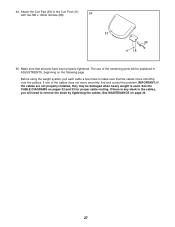
... If there is used. See MAINTENANCE on pages 32 and 33 for proper cable routing. Make sure that the cables move smoothly, find and correct the problem. See the CABLE DIAGRAMS on page 34. 27 IMPORTANT: If the cables are not properly installed, they may be damaged when heavy weight is any ...slack in the cables, you will be explained in ADJUSTMENTS, beginning on the following page. Attach the Curl Pad ...
... If there is used. See MAINTENANCE on pages 32 and 33 for proper cable routing. Make sure that the cables move smoothly, find and correct the problem. See the CABLE DIAGRAMS on page 34. 27 IMPORTANT: If the cables are not properly installed, they may be damaged when heavy weight is any ...slack in the cables, you will be explained in ADJUSTMENTS, beginning on the following page. Attach the Curl Pad ...
English Manual
Page 32
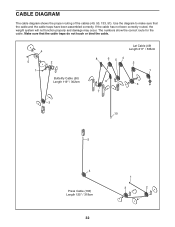
CABLE DIAGRAM The cable diagram shows the proper routing of the cables (49, 50, 133, 51). The numbers show the correct route for the cable. Make sure that the cable and the cable traps have been assembled correctly. Use the diagram to make sure that the cable traps do not touch or bind the cable. 4 5 1 2 Butterfly Cable (50) Length 119" / 302cm 3 Lat Cable (49) Length 211" / 536cm 8 6 54 2 1 9 3 7 10 5 4 Press Cable (133) Length 125" / 318cm 32 1 3 2 If the cable has not been correctly routed, the weight system will not function properly and damage may occur.
CABLE DIAGRAM The cable diagram shows the proper routing of the cables (49, 50, 133, 51). The numbers show the correct route for the cable. Make sure that the cable and the cable traps have been assembled correctly. Use the diagram to make sure that the cable traps do not touch or bind the cable. 4 5 1 2 Butterfly Cable (50) Length 119" / 302cm 3 Lat Cable (49) Length 211" / 536cm 8 6 54 2 1 9 3 7 10 5 4 Press Cable (133) Length 125" / 318cm 32 1 3 2 If the cable has not been correctly routed, the weight system will not function properly and damage may occur.

