
English Manual
Page 2
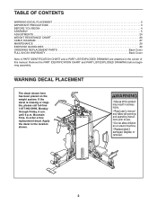
... LIST/EXPLODED DRAWING before beginning assembly. until 6 p.m. TABLE OF CONTENTS WARNING DECAL PLACEMENT 2 IMPORTANT PRECAUTIONS 3 BEFORE YOU BEGIN 4 ASSEMBLY 5 ADJUSTMENTS 24 WEIGHT RESISTANCE CHART 26 CABLE DIAGRAM 27 MAINTENANCE 29 EXERCISE GUIDELINES 30 ORDERING REPLACEMENT PARTS Back Cover FULL 90-DAY WARRANTY Back Cover Note: A PART IDENTIFICATION CHART and a PART LIST/EXPLODED...
... LIST/EXPLODED DRAWING before beginning assembly. until 6 p.m. TABLE OF CONTENTS WARNING DECAL PLACEMENT 2 IMPORTANT PRECAUTIONS 3 BEFORE YOU BEGIN 4 ASSEMBLY 5 ADJUSTMENTS 24 WEIGHT RESISTANCE CHART 26 CABLE DIAGRAM 27 MAINTENANCE 29 EXERCISE GUIDELINES 30 ORDERING REPLACEMENT PARTS Back Cover FULL 90-DAY WARRANTY Back Cover Note: A PART IDENTIFICATION CHART and a PART LIST/EXPLODED...
English Manual
Page 13
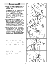
...Top Frame (7) and over a 90mm Pulley (39). Cable Assembly 22. Make sure the Cable is between the Pulley and the rod in the Top Frame. Refer to the CABLE DIAGRAMS on pages 27 and 28 as shown. 22 71...116), two 19mm Spacers (77), and an M10 Nylon Locknut (114). 24. Locate the Lat Cable (71). Make sure the Cable is between the Pulley and the rod in the Top Frame. Attach the Pulley inside the Top ...73) and an M10 Nylon Locknut (114). 73 71 125 41 114 7 13 Attach the Pulley, a Small Cable Trap (48), and two Half Finger Guards (42) at the second hole from the top of the two Pulley ...
...Top Frame (7) and over a 90mm Pulley (39). Cable Assembly 22. Make sure the Cable is between the Pulley and the rod in the Top Frame. Refer to the CABLE DIAGRAMS on pages 27 and 28 as shown. 22 71...116), two 19mm Spacers (77), and an M10 Nylon Locknut (114). 24. Locate the Lat Cable (71). Make sure the Cable is between the Pulley and the rod in the Top Frame. Attach the Pulley inside the Top ...73) and an M10 Nylon Locknut (114). 73 71 125 41 114 7 13 Attach the Pulley, a Small Cable Trap (48), and two Half Finger Guards (42) at the second hole from the top of the two Pulley ...
English Manual
Page 23
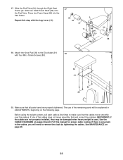
... will need to make sure that all parts have been properly tightened. IMPORTANT: If the cables are not properly installed, they may be explained in the cables, you will be damaged when heavy weight is used. See the CABLE DIAGRAMS on page 29. 23 Attach the Knee Pad (30) to the Dip Assist (21...) 68 with the Leg Lever (11). 67 58 9 32 31 11 32 58 68. If one of this step with four M6 x 16mm Screws (85). 30 21 85 85 69. Repeat this manual for proper cable...
... will need to make sure that all parts have been properly tightened. IMPORTANT: If the cables are not properly installed, they may be explained in the cables, you will be damaged when heavy weight is used. See the CABLE DIAGRAMS on page 29. 23 Attach the Knee Pad (30) to the Dip Assist (21...) 68 with the Leg Lever (11). 67 58 9 32 31 11 32 58 68. If one of this step with four M6 x 16mm Screws (85). 30 21 85 85 69. Repeat this manual for proper cable...
English Manual
Page 27
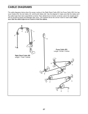
... touch or bind the cables. 43 1 5 2 6 Right Stack Cable (68) Length: 7 feet 7 inches 9 Press Cable (69) Length: 15 feet 7 inches 6 8 4 7 5 3 2 1 27 CABLE DIAGRAMS The cable diagrams below show the correct route for each cable. The numbers show the proper routing of the Right Stack Cable (68), the Press Cable (69), the Leg Lever Cable (70), the Lat Cable (71), and the Ab...
... touch or bind the cables. 43 1 5 2 6 Right Stack Cable (68) Length: 7 feet 7 inches 9 Press Cable (69) Length: 15 feet 7 inches 6 8 4 7 5 3 2 1 27 CABLE DIAGRAMS The cable diagrams below show the correct route for each cable. The numbers show the proper routing of the Right Stack Cable (68), the Press Cable (69), the Leg Lever Cable (70), the Lat Cable (71), and the Ab...


