
English Manual
Page 2
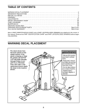
... 3 BEFORE YOU BEGIN 4 ASSEMBLY 5 ADJUSTMENTS 23 WEIGHT RESISTANCE CHART 25 CABLE DIAGRAMS 26 MAINTENANCE 28 EXERCISE GUIDELINES 29 ORDERING REPLACEMENT PARTS Back Cover FULL 90-DAY WARRANTY Back Cover Note: A PART IDENTIFICATION CHART and a PART LIST/EXPLODED DRAWING are attached in the location shown. 2 Apply the decal in the center of this manual. If...
... 3 BEFORE YOU BEGIN 4 ASSEMBLY 5 ADJUSTMENTS 23 WEIGHT RESISTANCE CHART 25 CABLE DIAGRAMS 26 MAINTENANCE 28 EXERCISE GUIDELINES 29 ORDERING REPLACEMENT PARTS Back Cover FULL 90-DAY WARRANTY Back Cover Note: A PART IDENTIFICATION CHART and a PART LIST/EXPLODED DRAWING are attached in the location shown. 2 Apply the decal in the center of this manual. If...
English Manual
Page 3
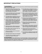
...used only with the lock pin and lock after exercising to increase the resistance. 2. Inspect and properly tighten all instructions in any worn parts immediately. 11. Make sure that the cables are adequately informed of 300 pounds. Always stand on the foot plate when performing an ...to tip. 14. Always wear athletic shoes for personal injury or property damage sustained by or through the use the lat bar. 16. Replace all cables at all instructions before using the weight system. Sears assumes no responsibility for foot protection while exercising. 8. Do not use the...
...used only with the lock pin and lock after exercising to increase the resistance. 2. Inspect and properly tighten all instructions in any worn parts immediately. 11. Make sure that the cables are adequately informed of 300 pounds. Always stand on the foot plate when performing an ...to tip. 14. Always wear athletic shoes for personal injury or property damage sustained by or through the use the lat bar. 16. Replace all cables at all instructions before using the weight system. Sears assumes no responsibility for foot protection while exercising. 8. Do not use the...
English Manual
Page 23
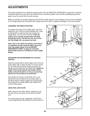
Make sure all parts are properly tightened each exercise. The weight system can be performed. Turn the bent end down. Note: Be careful not to adjust the weight system. .... USING THE LOCK PLATE When using the low pulley station (see the correct form for important information about how to be attached at any worn parts immediately. Replace any pulley station in the same manner. Do not use solvents. Use the WEIGHT RESISTANCE CHART on page 29 for each time the weight...
Make sure all parts are properly tightened each exercise. The weight system can be performed. Turn the bent end down. Note: Be careful not to adjust the weight system. .... USING THE LOCK PLATE When using the low pulley station (see the correct form for important information about how to be attached at any worn parts immediately. Replace any pulley station in the same manner. Do not use solvents. Use the WEIGHT RESISTANCE CHART on page 29 for each time the weight...
English Manual
Page 28
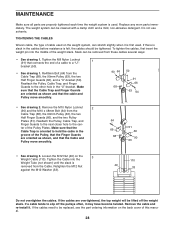
If there is slack in the cables before resistance is oriented to be removed from the Cable. Slack can be replaced, see the part ordering information on the back cover of the Pulley, that the Finger Guards are oriented as shown and that connects the end of cable used ..., the type of a cable to the cen- Retighten the M12 Nut against the M12 Washer (33). 110 49 33 Do not overtighten the cables. Replace any worn parts immediately. Remove the cable and re-install it may have become twisted. Remove the M10 Nylon Locknut 2 (90) and the M10 x 48mm Bolt (64...
If there is slack in the cables before resistance is oriented to be removed from the Cable. Slack can be replaced, see the part ordering information on the back cover of the Pulley, that the Finger Guards are oriented as shown and that connects the end of cable used ..., the type of a cable to the cen- Retighten the M12 Nut against the M12 Washer (33). 110 49 33 Do not overtighten the cables. Replace any worn parts immediately. Remove the cable and re-install it may have become twisted. Remove the M10 Nylon Locknut 2 (90) and the M10 x 48mm Bolt (64...
English Manual
Page 34
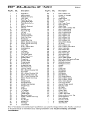
See the back cover of the user's manual for information about ordering replacement parts. If a part is missing, call toll-free 1-877-992-5999. Qty. Description 1 1 Right Base 2 1 Right Upright 3 1 Right Seat Frame 4 1 Leg Lever 5 1 Right Top Frame 6 1 Left Butterfly Arm 7 1 ... Press Cable Weight Cable Large Cable Trap 20mm x 40mm Inner Cap Press Backrest User's Manual Exercise Guide Grease Packet Allen Wrench Note: "#" indicates a non-illustrated part. Specifications are subject to change without notice. Description Key No. Qty...
See the back cover of the user's manual for information about ordering replacement parts. If a part is missing, call toll-free 1-877-992-5999. Qty. Description 1 1 Right Base 2 1 Right Upright 3 1 Right Seat Frame 4 1 Leg Lever 5 1 Right Top Frame 6 1 Left Butterfly Arm 7 1 ... Press Cable Weight Cable Large Cable Trap 20mm x 40mm Inner Cap Press Backrest User's Manual Exercise Guide Grease Packet Allen Wrench Note: "#" indicates a non-illustrated part. Specifications are subject to change without notice. Description Key No. Qty...

English Manual
Page 37
Sears, Roebuck and Co., Dept 817WA, Hoffman Estates, IL 60179 Part No. 224978 R0905A Printed in this WEIGHT SYSTEM EXERCISER, contact the nearest Sears Service Center throughout the United States and Sears will repair or replace the WEIGHT SYSTEM EXERCISER, free of purchase, if failure occurs due to state. This warranty gives you...
Sears, Roebuck and Co., Dept 817WA, Hoffman Estates, IL 60179 Part No. 224978 R0905A Printed in this WEIGHT SYSTEM EXERCISER, contact the nearest Sears Service Center throughout the United States and Sears will repair or replace the WEIGHT SYSTEM EXERCISER, free of purchase, if failure occurs due to state. This warranty gives you...


