

English Manual
Page 2
TABLE OF CONTENTS IMPORTANT PRECAUTIONS 3 BEFORE YOU BEGIN 4 ASSEMBLY 5 ADJUSTMENTS 21 WEIGHT RESISTANCE CHART 23 CABLE DIAGRAM 24 EXERCISE GUIDELINES 26 ORDERING REPLACEMENT PARTS Back Cover FULL 90 DAY WARRANTY Back Cover Note: A PART IDENTIFICATION CHART and a PART LIST/EXPLODED DRAWING are attached in the center of this manual. Remove the PART IDENTIFICATION CHART and the PART LIST/EXPLODED DRAWING before beginning assembly. 2
TABLE OF CONTENTS IMPORTANT PRECAUTIONS 3 BEFORE YOU BEGIN 4 ASSEMBLY 5 ADJUSTMENTS 21 WEIGHT RESISTANCE CHART 23 CABLE DIAGRAM 24 EXERCISE GUIDELINES 26 ORDERING REPLACEMENT PARTS Back Cover FULL 90 DAY WARRANTY Back Cover Note: A PART IDENTIFICATION CHART and a PART LIST/EXPLODED DRAWING are attached in the center of this manual. Remove the PART IDENTIFICATION CHART and the PART LIST/EXPLODED DRAWING before beginning assembly. 2
English Manual
Page 4
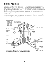
ASSEMBLED DIMENSIONS: Height: 77 in the manual. they do not correspond to tone your body, build dramatic muscle ..., please call our toll-free HELPLINE at 1-800-736-6879, Monday through Saturday, 7 a.m. If you for selecting the versatile WEIDER® PRO 4100 weight system. To help you to the weight system (see the front cover of the right upright.) Butterfly Arm /Press Arm ... to develop every major muscle group of the body. For your goal is 831.159823. The PRO 4100 weight system offers a selection of weight stations designed to a person facing away from the weight system;
ASSEMBLED DIMENSIONS: Height: 77 in the manual. they do not correspond to tone your body, build dramatic muscle ..., please call our toll-free HELPLINE at 1-800-736-6879, Monday through Saturday, 7 a.m. If you for selecting the versatile WEIDER® PRO 4100 weight system. To help you to the weight system (see the front cover of the right upright.) Butterfly Arm /Press Arm ... to develop every major muscle group of the body. For your goal is 831.159823. The PRO 4100 weight system offers a selection of weight stations designed to a person facing away from the weight system;
English Manual
Page 5
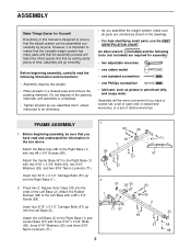
...screwdriver • one Phillips screwdriver • lubricant, such as shown in the drawings. • For help identifying small parts, use the PART IDENTIFICATION CHART. FRAME ASSEMBLY 1. Press two 2" Square Inner Caps (33) into the Left Base (2). Insert four 5/16" x 2 1/2" Carriage Bolts (57) up into the Right Base...plenty of ratchet wrenches. Insert four 5/16" x 2 1/2" Carriage Bolts (57) up into the ends of the packing materials until assembly is completed. • Tighten all parts in this manual is important to realize that the versatile weight system has many parts and ...
...screwdriver • one Phillips screwdriver • lubricant, such as shown in the drawings. • For help identifying small parts, use the PART IDENTIFICATION CHART. FRAME ASSEMBLY 1. Press two 2" Square Inner Caps (33) into the Left Base (2). Insert four 5/16" x 2 1/2" Carriage Bolts (57) up into the Right Base...plenty of ratchet wrenches. Insert four 5/16" x 2 1/2" Carriage Bolts (57) up into the ends of the packing materials until assembly is completed. • Tighten all parts in this manual is important to realize that the versatile weight system has many parts and ...
English Manual
Page 9
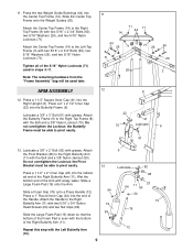
... Inner Cap (24) into the Center Top Frame (14). Note: The remaining hardware from the "Frame Assembly" bag will be able to the Left Top Frame (3) with the Bolt and a 3/8" Nylon Locknut (70). ARM ASSEMBLY 12. Press the two Weight Guide Bushings (44) into the end of the Right Butterfly Arm (11...
... Inner Cap (24) into the Center Top Frame (14). Note: The remaining hardware from the "Frame Assembly" bag will be able to the Left Top Frame (3) with the Bolt and a 3/8" Nylon Locknut (70). ARM ASSEMBLY 12. Press the two Weight Guide Bushings (44) into the end of the Right Butterfly Arm (11...
English Manual
Page 11
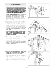
...) from 20 the left side of the bracket on pages 24 and 25 for clarity. Wrap the High Cable (45) around a 3 1/2" Pulley (38). IMPORTANT: While assembling the cables, do not over tighten the locknuts attaching the pulleys; Be sure the Cable Trap is completed. 19. Note: To complete this step is... and help identifying the cables. Wrap the High Cable (45) around a 3 1/2" Pulley (38) and down through the Left Top Frame (3) and around a 3 1/2" Pulley (38). CABLE ASSEMBLY 17.
...) from 20 the left side of the bracket on pages 24 and 25 for clarity. Wrap the High Cable (45) around a 3 1/2" Pulley (38). IMPORTANT: While assembling the cables, do not over tighten the locknuts attaching the pulleys; Be sure the Cable Trap is completed. 19. Note: To complete this step is... and help identifying the cables. Wrap the High Cable (45) around a 3 1/2" Pulley (38) and down through the Left Top Frame (3) and around a 3 1/2" Pulley (38). CABLE ASSEMBLY 17.
English Manual
Page 19
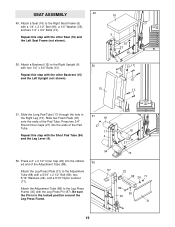
SEAT ASSEMBLY 49 49. Attach a Backrest (15) to the Adjustment Tube (88) with a 5/16" x 2 1/2" Bolt (89), two 5/16" Washers (26), and a 5/16" Nylon Locknut (71). Slide two ...
SEAT ASSEMBLY 49 49. Attach a Backrest (15) to the Adjustment Tube (88) with a 5/16" x 2 1/2" Bolt (89), two 5/16" Washers (26), and a 5/16" Nylon Locknut (71). Slide two ...
English Manual
Page 24
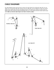
... traps do not touch or bind the cables. 2 5 4 1 Butterfly Cable (46) 3 4 2 5 3 1 High Cable (45) 6 6 11 Low Cable (47) 7 9 8 10 3 5 4 2 1 24 If the cables have been assembled correctly. The numbers show the proper routing of the High Cable (45), the Butterfly Cable (46), the Low Cable (47), the Leg Press Cable (95...
... traps do not touch or bind the cables. 2 5 4 1 Butterfly Cable (46) 3 4 2 5 3 1 High Cable (45) 6 6 11 Low Cable (47) 7 9 8 10 3 5 4 2 1 24 If the cables have been assembled correctly. The numbers show the proper routing of the High Cable (45), the Butterfly Cable (46), the Low Cable (47), the Leg Press Cable (95...


