

Canadian English Manual
Page 1
... CUSTOMER SERVICE DEPARTMENT DIRECTLY. CALL TOLL-FREE: 1-888-936-4266 Mon.-Fri., 8:00 until 17:00 EST (excluding holidays) OR E-MAIL US: [email protected] CAUTION Read all precautions and instructions in the space above for future reference. Save this equipment. Model No. 30664.0 Serial No. Serial Number Decal QUESTIONS? Write the serial number in this manual before using this manual for future reference. USER'S MANUAL...
... CUSTOMER SERVICE DEPARTMENT DIRECTLY. CALL TOLL-FREE: 1-888-936-4266 Mon.-Fri., 8:00 until 17:00 EST (excluding holidays) OR E-MAIL US: [email protected] CAUTION Read all precautions and instructions in the space above for future reference. Save this equipment. Model No. 30664.0 Serial No. Serial Number Decal QUESTIONS? Write the serial number in this manual before using this manual for future reference. USER'S MANUAL...
Canadian English Manual
Page 2
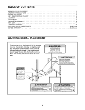
... not be shown at actual size. Part # 267062 2 TABLE OF CONTENTS WARNING DECAL PLACEMENT 2 IMPORTANT PRECAUTIONS 3 BEFORE YOU BEGIN 4 PART IDENTIFICATION CHART 5 ASSEMBLY 6 ADJUSTMENT 10 EXERCISE GUIDELINES 12 PART LIST 14 EXPLODED DRAWING 15 ORDERING REPLACEMENT PARTS Back Cover LIMITED WARRANTY Back Cover WARNING DECAL PLACEMENT This drawing shows the location(s) of this manual and request a free replacement decal. Apply the decal in the location shown. Keep hands and fingers...
... not be shown at actual size. Part # 267062 2 TABLE OF CONTENTS WARNING DECAL PLACEMENT 2 IMPORTANT PRECAUTIONS 3 BEFORE YOU BEGIN 4 PART IDENTIFICATION CHART 5 ASSEMBLY 6 ADJUSTMENT 10 EXERCISE GUIDELINES 12 PART LIST 14 EXPLODED DRAWING 15 ORDERING REPLACEMENT PARTS Back Cover LIMITED WARRANTY Back Cover WARNING DECAL PLACEMENT This drawing shows the location(s) of this manual and request a free replacement decal. Apply the decal in the location shown. Keep hands and fingers...

Canadian English Manual
Page 3
... to support a maximum user weight of 300 lbs. (136 kg) and a maximum total weight of 410 lbs. (186 kg). Do not place more than 110 lbs. (50 kg) on the weight carriage. Replace any exercise program, consult your weight bench. Always remove the curl post and the lat tower from the front leg before using your physician. The weight bench is an equal amount of weight on...
... to support a maximum user weight of 300 lbs. (136 kg) and a maximum total weight of 410 lbs. (186 kg). Do not place more than 110 lbs. (50 kg) on the weight carriage. Replace any exercise program, consult your weight bench. Always remove the curl post and the lat tower from the front leg before using your physician. The weight bench is an equal amount of weight on...

Canadian English Manual
Page 4
... achieve the specific results you , note the product model number and serial number before using the weight bench. The model number and the location of the serial number decal are shown on the front cover of this manual. Before reading further, please review the drawing below and familiarize yourself with the labeled parts. To help you for selecting the WEIDER PRO™ 290 W weight bench. For your body, build dramatic muscle size and strength...
... achieve the specific results you , note the product model number and serial number before using the weight bench. The model number and the location of the serial number decal are shown on the front cover of this manual. Before reading further, please review the drawing below and familiarize yourself with the labeled parts. To help you for selecting the WEIDER PRO™ 290 W weight bench. For your body, build dramatic muscle size and strength...

Canadian English Manual
Page 5
... Screw (29) M10 Washer (34) 5 If a part is provided to see if it has been preattached. PART IDENTIFICATION CHART This chart is not in the hardware kit, check to help you identify the small parts used in parentheses below each part refers to the key number of the part from the PART LIST near the end of this manual. The number in assembly. Note: Some small parts...
... Screw (29) M10 Washer (34) 5 If a part is provided to see if it has been preattached. PART IDENTIFICATION CHART This chart is not in the hardware kit, check to help you identify the small parts used in parentheses below each part refers to the key number of the part from the PART LIST near the end of this manual. The number in assembly. Note: Some small parts...

Canadian English Manual
Page 6
... Everything in this manual is completed. • For help identifying small parts, use the PART IDENTIFICATION CHART on top. Attach the Crossbar to walk around the weight bench as shown in the drawings. • Tighten all parts in the box above. Attach the Front Leg (8) 2 to the other Upright (1) in the same way. 1 3 18 Warning Decals 18 1 16 17 2. Before assembling the weight bench, 1 make sure all...
... Everything in this manual is completed. • For help identifying small parts, use the PART IDENTIFICATION CHART on top. Attach the Crossbar to walk around the weight bench as shown in the drawings. • Tighten all parts in the box above. Attach the Front Leg (8) 2 to the other Upright (1) in the same way. 1 3 18 Warning Decals 18 1 16 17 2. Before assembling the weight bench, 1 make sure all...
Canadian English Manual
Page 7
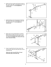
... M8 Locknuts (17); Attach the Leg Lever (4) to the Frame (2) with the Bolt and an M10 Locknut (33). Attach the Frame (2) to an M10 x 63mm Bolt (32). Do not overtighten the Locknut; Attach the other Long Pad Tube (10) and Foam Pads (23) in the Leg Lever (4). do not tighten the Locknuts yet. 18... 16 17 2 3 18 17 5. Apply some of the included grease to the Crossbar (3) with three 4 M8 x 55mm Bolts (18), two M8 Washers (16), and three M8 Locknuts (17); Slide two ...
... M8 Locknuts (17); Attach the Leg Lever (4) to the Frame (2) with the Bolt and an M10 Locknut (33). Attach the Frame (2) to an M10 x 63mm Bolt (32). Do not overtighten the Locknut; Attach the other Long Pad Tube (10) and Foam Pads (23) in the Leg Lever (4). do not tighten the Locknuts yet. 18... 16 17 2 3 18 17 5. Apply some of the included grease to the Crossbar (3) with three 4 M8 x 55mm Bolts (18), two M8 Washers (16), and three M8 Locknuts (17); Slide two ...

Canadian English Manual
Page 8
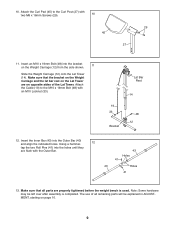
... 8. Rotate the Backrest Support to the Frame (2) with the locking pin wrapped around the left Upright. See step 7. Tighten the M6 x 38mm Screws (30). 8 1 Grease 34 36 5 2 Welded Tube 33 34 9. Grease an M10 x 137mm Bolt (36). Do not overtighten the Locknut; 7. Attach the Seat (11) to the locked position, with four M6 x 16mm Screws (29). 9 11 2 1 7 Locking Pin 29 8 Tighten the M8 Locknuts...
... 8. Rotate the Backrest Support to the Frame (2) with the locking pin wrapped around the left Upright. See step 7. Tighten the M6 x 38mm Screws (30). 8 1 Grease 34 36 5 2 Welded Tube 33 34 9. Grease an M10 x 137mm Bolt (36). Do not overtighten the Locknut; 7. Attach the Seat (11) to the locked position, with four M6 x 16mm Screws (29). 9 11 2 1 7 Locking Pin 29 8 Tighten the M8 Locknuts...
Canadian English Manual
Page 9
... parts will be left over after assembly is used. Insert the Inner Bar (43) into the bracket on page 10. 9 Note: Some hardware may be explained in ADJUSTMENT, starting on the Weight Carriage (12) from the side shown. 11 Slide the Weight Carriage (12) onto the Lat Tower (14). The use of the Lat Tower. Using a hammer, 12 tap the two Roll Pins...
... parts will be left over after assembly is used. Insert the Inner Bar (43) into the bracket on page 10. 9 Note: Some hardware may be explained in ADJUSTMENT, starting on the Weight Carriage (12) from the side shown. 11 Slide the Weight Carriage (12) onto the Lat Tower (14). The use of the Lat Tower. Using a hammer, 12 tap the two Roll Pins...

Canadian English Manual
Page 10
... the Leg Lever (4). To use solvents to see the correct form for several exercises. ADJUSTING THE BACKREST The Backrest (6) can be used . ADJUSTMENT The steps below explain how the weight bench can be adjusted. Rest the Backrest on the Backrest Support. 1 6 1 7 3 Locking Pin ATTACHING WEIGHTS TO THE WEIGHT CARRIAGE OR THE LEG LEVER To use the Leg Lever (4), slide the desired Weights (38, 44) onto the weight tube on the weight rests...
... the Leg Lever (4). To use solvents to see the correct form for several exercises. ADJUSTING THE BACKREST The Backrest (6) can be used . ADJUSTMENT The steps below explain how the weight bench can be adjusted. Rest the Backrest on the Backrest Support. 1 6 1 7 3 Locking Pin ATTACHING WEIGHTS TO THE WEIGHT CARRIAGE OR THE LEG LEVER To use the Leg Lever (4), slide the desired Weights (38, 44) onto the weight tube on the weight rests...

Canadian English Manual
Page 11
... 42 ATTACHING THE CURL PAD OR THE LAT TOWER For some exercises, the Curl Pad (45) must be attached in the Front Leg. The Lat Tower (14) can be attached to the Cable (19) with the Curl Knob (31). Insert the Curl Post (27) into the Front Leg (8). 45 27 14 Hole 22 Adjustment Hole 31 8 ATTACHING THE LAT BAR Attach the Lat Bar (15) to the weight bench.
... 42 ATTACHING THE CURL PAD OR THE LAT TOWER For some exercises, the Curl Pad (45) must be attached in the Front Leg. The Lat Tower (14) can be attached to the Cable (19) with the Curl Knob (31). Insert the Curl Post (27) into the Front Leg (8). 45 27 14 Hole 22 Adjustment Hole 31 8 ATTACHING THE LAT BAR Attach the Lat Bar (15) to the weight bench.

Canadian English Manual
Page 12
... while exercising, stop immediately and cool down. Weight Loss To lose weight, use a low amount of resistance and increase the number of repetitions in two ways: • by changing the amount of resistance used • by using high amounts of an individual exercise in each workout with it during the first few months of your body for a maximum of an effective exercise program. You can adjust the...
... while exercising, stop immediately and cool down. Weight Loss To lose weight, use a low amount of resistance and increase the number of repetitions in two ways: • by changing the amount of resistance used • by using high amounts of an individual exercise in each workout with it during the first few months of your body for a maximum of an effective exercise program. You can adjust the...

Canadian English Manual
Page 13
... exertion stroke of time after each set for a short period of each workout. Rest for a weight loss workout. COOLING DOWN End each workout with the equipment and learning the proper form for both your weight and key body measurements at the end of arm) D. Write the date, the exercises performed, the resistance used, and the numbers of leg) X. Pectoralis Major (chest) C. Hip Flexors (upper thigh) G. Adductor...
... exertion stroke of time after each set for a short period of each workout. Rest for a weight loss workout. COOLING DOWN End each workout with the equipment and learning the proper form for both your weight and key body measurements at the end of arm) D. Write the date, the exercises performed, the resistance used, and the numbers of leg) X. Pectoralis Major (chest) C. Hip Flexors (upper thigh) G. Adductor...

Canadian English Manual
Page 14
... 2 10mm Large Spacer 50 1 Cable Clip 51 2 Small Weight Collar 52 2 Weight Spacer * - Grease Packet Note: Specifications are not illustrated. 14 PART LIST-Model No. 30664.0 R0808A Key No. Exercise Guide * - Description 1 2 Upright 2 1 Frame 3 1 Crossbar 4 1 Leg Lever 5 2 Backrest Tube 6 1 Backrest 7 1 Backrest Support 8 1 Front Leg 9 6 19mm Round Inner Cap 10 2 Long Pad Tube 11 1 Seat 12 1 Weight Carriage 13 1 Stabilizer 14 1 Lat Tower 15 1 Lat Bar 16 8 M8 Washer 17 11...
... 2 10mm Large Spacer 50 1 Cable Clip 51 2 Small Weight Collar 52 2 Weight Spacer * - Grease Packet Note: Specifications are not illustrated. 14 PART LIST-Model No. 30664.0 R0808A Key No. Exercise Guide * - Description 1 2 Upright 2 1 Frame 3 1 Crossbar 4 1 Leg Lever 5 2 Backrest Tube 6 1 Backrest 7 1 Backrest Support 8 1 Front Leg 9 6 19mm Round Inner Cap 10 2 Long Pad Tube 11 1 Seat 12 1 Weight Carriage 13 1 Stabilizer 14 1 Lat Tower 15 1 Lat Bar 16 8 M8 Washer 17 11...

Canadian English Manual
Page 15
EXPLODED DRAWING-Model No. 30664.0 R0808A 24 28 15 22 6 35 33 49 34 25 51 52 19 33 24 12 23 19 28 49 34 47 24 1 50 16 17 16 14 52 51 46 48 32 21 11 39 22 8 46 24 17 22 4 33 17 13 5 26 36 9 34 7 35 30 26 34 33 30 9 21 18 18 3 16 17 1 18 2 17 18 18 18 16 29 17 44 38 40 21 41 24 22 24 9 20 37 9 10 22 10 22 24 42 38 9 43 45 27 9 23 16 17 16 21 42 29 31 15
EXPLODED DRAWING-Model No. 30664.0 R0808A 24 28 15 22 6 35 33 49 34 25 51 52 19 33 24 12 23 19 28 49 34 47 24 1 50 16 17 16 14 52 51 46 48 32 21 11 39 22 8 46 24 17 22 4 33 17 13 5 26 36 9 34 7 35 30 26 34 33 30 9 21 18 18 3 16 17 1 18 2 17 18 18 18 16 29 17 44 38 40 21 41 24 22 24 9 20 37 9 10 22 10 22 24 42 38 9 43 45 27 9 23 16 17 16 21 42 29 31 15

Canadian English Manual
Page 16
... front cover of this manual) • the key number and description of the replacement part(s) (see the front cover of this product to repairing or replacing, at ICONʼs option, the product through one of its authorized service centers. This warranty extends only to any implied warranties of removal or installation; products used as store display models. damages with the use , or costs of merchantability or fitness for which warranty claims...
... front cover of this manual) • the key number and description of the replacement part(s) (see the front cover of this product to repairing or replacing, at ICONʼs option, the product through one of its authorized service centers. This warranty extends only to any implied warranties of removal or installation; products used as store display models. damages with the use , or costs of merchantability or fitness for which warranty claims...


