

Uk Manual
Page 1
WEEVSY2026.0 Serial No. Write the serial number in this manual before using this manual for future reference. Serial Number Decal (Under Seat) QUESTIONS? If you have questions, or if there are committed to providing complete customer satisfaction. Unit 4 Revie Road Industrial Estate Revie Road Beeston Leeds, LS118JG UK email: [email protected] CAUTION Read all precautions and instructions in the space above for future reference. As a manufacturer, we are missing parts, please call: 08457 089 009 Or write: ICON Health & Fitness, Ltd. Save this equipment. USER'S MANUAL ...
WEEVSY2026.0 Serial No. Write the serial number in this manual before using this manual for future reference. Serial Number Decal (Under Seat) QUESTIONS? If you have questions, or if there are committed to providing complete customer satisfaction. Unit 4 Revie Road Industrial Estate Revie Road Beeston Leeds, LS118JG UK email: [email protected] CAUTION Read all precautions and instructions in the space above for future reference. As a manufacturer, we are missing parts, please call: 08457 089 009 Or write: ICON Health & Fitness, Ltd. Save this equipment. USER'S MANUAL ...
Uk Manual
Page 2
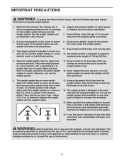
Apply the decal in the location shown. VERTICAL WARNING PN 218558 - Black Text/Clear Background PN 218559 - White Text/Clear Background WEIDER is missing or illegible, please call the telephone number on the weight system. If the decal is a registered trademark of this manual and order a free ...
Apply the decal in the location shown. VERTICAL WARNING PN 218558 - Black Text/Clear Background PN 218559 - White Text/Clear Background WEIDER is missing or illegible, please call the telephone number on the weight system. If the decal is a registered trademark of this manual and order a free ...
Uk Manual
Page 3
Place the weight system on a level surface, with a mat beneath it to be used only with dumbbells or any time while exercising, stop immediately and make sure that the cables remain on the weight system before using the weight system. 1. Do not use only. Inspect and properly tighten all instructions in this or any worn parts immediately. 7. Keep children under the age of view. Always stand on all of this manual. 6. Never release the arms, leg lever, or lat bar while weights are on the foot plate when performing an exercise that there is especially ...
Place the weight system on a level surface, with a mat beneath it to be used only with dumbbells or any time while exercising, stop immediately and make sure that the cables remain on the weight system before using the weight system. 1. Do not use only. Inspect and properly tighten all instructions in this or any worn parts immediately. 7. Keep children under the age of view. Always stand on all of this manual. 6. Never release the arms, leg lever, or lat bar while weights are on the foot plate when performing an exercise that there is especially ...
Uk Manual
Page 4
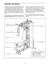
... before contacting us. BEFORE YOU BEGIN Thank you have questions after reading this manual, see the front cover of this manual for selecting the versatile WEIDER® PRO 2000 weight system. If you for the location of the body. The model number is to tone your body, build dramatic muscle size and strength...
... before contacting us. BEFORE YOU BEGIN Thank you have questions after reading this manual, see the front cover of this manual for selecting the versatile WEIDER® PRO 2000 weight system. If you for the location of the body. The model number is to tone your body, build dramatic muscle size and strength...
Uk Manual
Page 5
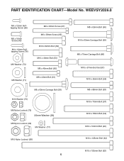
PART IDENTIFICATION CHART-Model No. WEEVSY2026.0 M4 x 12mm Selftapping Screw (56) M6 x 16mm Screw (40) M4 x 19mm Selftapping Screw (76) M6 Washer (73) M8 Washer (71) M6 x 63mm Screw (67) M6 x 58mm Screw (65) M10 x 52mm Bolt (52) M10 x 46mm Bolt (53) M8 x 45mm Bolt (60) M6 x 43mm Bolt (61) M8 x 63mm Carriage Bolt (58) M10 Washer (70) M6 Nylon Locknut (72) 25mm Washer (29) M8 Nylon Locknut (69) M4 Washer (77) M10 Nylon Locknut (68) 5 M8 x 63mm Bolt (66) M10 x 65mm Carriage Bolt (59) M8 x 70mm Carriage Bolt (86) M10 x 57mm Bolt Set (81) M10 x 65mm Bolt (55) M8 x 68mm Bolt (63) M10 x ...
PART IDENTIFICATION CHART-Model No. WEEVSY2026.0 M4 x 12mm Selftapping Screw (56) M6 x 16mm Screw (40) M4 x 19mm Selftapping Screw (76) M6 Washer (73) M8 Washer (71) M6 x 63mm Screw (67) M6 x 58mm Screw (65) M10 x 52mm Bolt (52) M10 x 46mm Bolt (53) M8 x 45mm Bolt (60) M6 x 43mm Bolt (61) M8 x 63mm Carriage Bolt (58) M10 Washer (70) M6 Nylon Locknut (72) 25mm Washer (29) M8 Nylon Locknut (69) M4 Washer (77) M10 Nylon Locknut (68) 5 M8 x 63mm Bolt (66) M10 x 65mm Carriage Bolt (59) M8 x 70mm Carriage Bolt (86) M10 x 57mm Bolt Set (81) M10 x 65mm Bolt (55) M8 x 68mm Bolt (63) M10 x ...
Uk Manual
Page 6
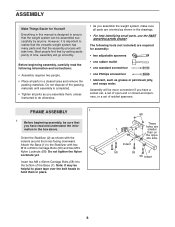
Do not dispose of ratchet spanners. Assembly will be sure that you have a socket set, a set of open-end or closed-end spanners, or a set of the packing materials until assembly is completed. • Tighten all parts as grease or petroleum jelly, and soapy water. FRAME ASSEMBLY 1 1. Before beginning assembly, be more convenient if you have read the following tools (not included) are required for Yourself Everything in this manual is designed to ensure that the weight system can be assembled successfully by setting aside plenty of the Base (1). The following information ...
Do not dispose of ratchet spanners. Assembly will be sure that you have a socket set, a set of open-end or closed-end spanners, or a set of the packing materials until assembly is completed. • Tighten all parts as grease or petroleum jelly, and soapy water. FRAME ASSEMBLY 1 1. Before beginning assembly, be more convenient if you have read the following tools (not included) are required for Yourself Everything in this manual is designed to ensure that the weight system can be assembled successfully by setting aside plenty of the Base (1). The following information ...
Uk Manual
Page 7
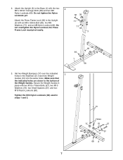
the Press Frame Lock must pivot easily. 66 39 71 71 69 3 69 69 1 58 3. Secure the Weight Guides in place with an M8 x 63mm Bolt (66), two M8 Washers (71), and an M8 Nylon Locknut (69). Tighten the M10 Nylon Locknuts (68) used in the Stabilizer (2). Attach the Press Frame Lock (39) to the Upright (3) with two M10 x 70mm Bolts (57), two M10 Washers (70), two Small Spacers (37), and two M10 Nylon Locknuts (68). Attach the Upright (3) to the bottom of the Weight Guides. Make sure that the indicated holes are closer to the Base (1) with the two 2 M8 x 63mm Carriage Bolts (58) ...
the Press Frame Lock must pivot easily. 66 39 71 71 69 3 69 69 1 58 3. Secure the Weight Guides in place with an M8 x 63mm Bolt (66), two M8 Washers (71), and an M8 Nylon Locknut (69). Tighten the M10 Nylon Locknuts (68) used in the Stabilizer (2). Attach the Press Frame Lock (39) to the Upright (3) with two M10 x 70mm Bolts (57), two M10 Washers (70), two Small Spacers (37), and two M10 Nylon Locknuts (68). Attach the Upright (3) to the bottom of the Weight Guides. Make sure that the indicated holes are closer to the Base (1) with the two 2 M8 x 63mm Carriage Bolts (58) ...
Uk Manual
Page 8
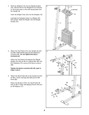
Slide ten Weights (15) onto the Weight Guides 4 (10), with an M10 x 155mm Bolt (62), two M10 Washers (70), and an M10 Nylon Locknut (68). Tighten the Nylon Locknuts (68, 69) used in a Weight (15) with an M8 x 70mm Carriage Bolt (86) and an M8 Knob (82). 4. Insert the Weight Tube (12) into the Weights (15). Lubricate the indicated holes in steps 2 and 5. 4 62 70 63 3 69 10 70 68 6. Do not tighten the Nylon Locknuts yet. Attach the Top Frame (4) between the Weight Guides (10) with the slot for the Weight Pin (not shown) on the bottom and on the side facing away from the Upright...
Slide ten Weights (15) onto the Weight Guides 4 (10), with an M10 x 155mm Bolt (62), two M10 Washers (70), and an M10 Nylon Locknut (68). Tighten the Nylon Locknuts (68, 69) used in a Weight (15) with an M8 x 70mm Carriage Bolt (86) and an M8 Knob (82). 4. Insert the Weight Tube (12) into the Weights (15). Lubricate the indicated holes in steps 2 and 5. 4 62 70 63 3 69 10 70 68 6. Do not tighten the Nylon Locknuts yet. Attach the Top Frame (4) between the Weight Guides (10) with the slot for the Weight Pin (not shown) on the bottom and on the side facing away from the Upright...

Uk Manual
Page 9
Do not overtighten the Bolt Set; Attach the Press Frame to the Seat Frame (8) with the bracket on the Seat Frame. Repeat this step with the Bolt, two M10 Washers (70), and an M10 Nylon Locknut (68). Make sure that the barrel of the Bolt Set is inserted through both sides of the bracket on the side shown. ARM ASSEMBLY 7 7. the Leg Lever must pivot easily. 8 64 70 4 Grease 70 68 9. Orient the Press Frame (5) with the Bolt Set. Grease 8 81 9 81 8. the Press Frame must pivot easily. Do not overtighten the Nylon Locknut; Grease the M10 x 57mm Bolt Set (...
Do not overtighten the Bolt Set; Attach the Press Frame to the Seat Frame (8) with the bracket on the Seat Frame. Repeat this step with the Bolt, two M10 Washers (70), and an M10 Nylon Locknut (68). Make sure that the barrel of the Bolt Set is inserted through both sides of the bracket on the side shown. ARM ASSEMBLY 7 7. the Leg Lever must pivot easily. 8 64 70 4 Grease 70 68 9. Orient the Press Frame (5) with the Bolt Set. Grease 8 81 9 81 8. the Press Frame must pivot easily. Do not overtighten the Nylon Locknut; Grease the M10 x 57mm Bolt Set (...
Uk Manual
Page 10
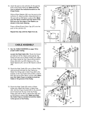
Press a 25mm Round Outer Cap (27) onto the post on the Left Arm (7) through the Top Frame (4). Attach the Pulley inside the Top Frame with the Right Arm (6). 10 6 Post 61 5 Bracket 61 72 27 29 72 7 CABLE ASSEMBLY 11 11. Insert the post on the Left Arm (7). 10. Attach an M6 x 43mm Bolt (61) to hold the Cable in the inset drawing. Route the threaded shaft end of the Pulley. 10 52 44 35 50 35 36 34 68 44 Route the High Cable (50) over a 90mm Pulley (34). Make sure the Cable Trap is oriented to the post with an M6 Nylon Locknut (72). Attach the Pulley, a ...
Press a 25mm Round Outer Cap (27) onto the post on the Left Arm (7) through the Top Frame (4). Attach the Pulley inside the Top Frame with the Right Arm (6). 10 6 Post 61 5 Bracket 61 72 27 29 72 7 CABLE ASSEMBLY 11 11. Insert the post on the Left Arm (7). 10. Attach an M6 x 43mm Bolt (61) to hold the Cable in the inset drawing. Route the threaded shaft end of the Pulley. 10 52 44 35 50 35 36 34 68 44 Route the High Cable (50) over a 90mm Pulley (34). Make sure the Cable Trap is oriented to the post with an M6 Nylon Locknut (72). Attach the Pulley, a ...
Uk Manual
Page 11
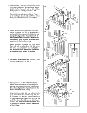
Attach the Pulley and two Finger Guards (35) to the Weight Tube (12) with an M10 x 46mm Bolt (53) and an M10 Nylon Locknut (68). Note: Do not completely tighten the Nylon Locknut; it should be threaded onto the Cable so that the Cable Trap is oriented to the indicated side of the Pulley. 11 7 54 35 36 68 38 52 34 35 70 3 49 Do not overtighten the Nylon Locknut; the Weight Tube must pivot easily. Do not overtighten the Nylon Locknut; 14. Attach the Small "U"-bracket (11) to the Top Frame (4) with an M8 x 45mm Bolt (60) and an M8 Nylon Locknut (69). Attach ...
Attach the Pulley and two Finger Guards (35) to the Weight Tube (12) with an M10 x 46mm Bolt (53) and an M10 Nylon Locknut (68). Note: Do not completely tighten the Nylon Locknut; it should be threaded onto the Cable so that the Cable Trap is oriented to the indicated side of the Pulley. 11 7 54 35 36 68 38 52 34 35 70 3 49 Do not overtighten the Nylon Locknut; the Weight Tube must pivot easily. Do not overtighten the Nylon Locknut; 14. Attach the Small "U"-bracket (11) to the Top Frame (4) with an M8 x 45mm Bolt (60) and an M8 Nylon Locknut (69). Attach ...

Uk Manual
Page 12
Do not overtighten the Nylon Locknut; Make sure that the Cable Trap is oriented to the indicated side of a Pulley Arm (38) with an M10 x 46mm Bolt (53) and an M10 Nylon Locknut (68). 49 34 35 68 35 53 42 19. Locate the Short Cable (47). Attach the Pulley, a Cable Trap (36), an M10 Washer (70), and two Finger Guards (35) to hold the Cable in the groove of the Press Cable (49) onto the hook on the Cable to the Base (1) with the Bolt and an M10 Nylon Locknut (68). Apply grease to an M10 x 78mm Bolt (54). 19 Attach a Pulley Arm (38) to the Double "U"-bracket (42) with ...
Do not overtighten the Nylon Locknut; Make sure that the Cable Trap is oriented to the indicated side of a Pulley Arm (38) with an M10 x 46mm Bolt (53) and an M10 Nylon Locknut (68). 49 34 35 68 35 53 42 19. Locate the Short Cable (47). Attach the Pulley, a Cable Trap (36), an M10 Washer (70), and two Finger Guards (35) to hold the Cable in the groove of the Press Cable (49) onto the hook on the Cable to the Base (1) with the Bolt and an M10 Nylon Locknut (68). Apply grease to an M10 x 78mm Bolt (54). 19 Attach a Pulley Arm (38) to the Double "U"-bracket (42) with ...
Uk Manual
Page 13
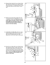
Attach the Pulley and two Finger Guards (35) to hold the Cable in the inset drawing. 47 43 69 47 43 71 69 24. Attach the Cable 24 inside the Base (1) with an M8 Washer (71) and an M8 Nylon Locknut (69). Make sure that two threads show past the Nylon Locknut, as shown in the groove of the two Pulley Plates (44) with an M10 x 46mm Bolt (53) and an M10 Nylon Locknut (68). 53 35 35 42 68 47 34 23. it should be threaded onto the Cable so that the Cable Trap is oriented to the Double "U"-bracket (42) with an M10 x 52mm Bolt (52) and an M10 Nylon Locknut (68). ...
Attach the Pulley and two Finger Guards (35) to hold the Cable in the inset drawing. 47 43 69 47 43 71 69 24. Attach the Cable 24 inside the Base (1) with an M8 Washer (71) and an M8 Nylon Locknut (69). Make sure that two threads show past the Nylon Locknut, as shown in the groove of the two Pulley Plates (44) with an M10 x 46mm Bolt (53) and an M10 Nylon Locknut (68). 53 35 35 42 68 47 34 23. it should be threaded onto the Cable so that the Cable Trap is oriented to the Double "U"-bracket (42) with an M10 x 52mm Bolt (52) and an M10 Nylon Locknut (68). ...
Uk Manual
Page 14
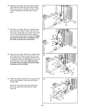
Route the Low Cable (48) under a 90mm Pulley 26 (34). Attach the Pulley, a Cable Trap (36), and two Guards (14) to the Upright (3) with an M10 Washer (70) and an M10 Nylon Locknut (68). Wrap the Low Cable (48) under a 90mm Pulley 28 (34). Make sure that the Cable Trap is oriented to the bracket on the Base (1) with two Cable Clips (33). 14 3 68 70 34 14 14 70 48 36 46 9 83 48 30 70 33 68 Attach the Cable Hook (30) to hold the Cable in the "U"-bracket (43) with an M10 x 52mm Bolt (52) and an M10 Nylon Locknut (68). Route the Low Cable (48) over a 90mm Pulley...
Route the Low Cable (48) under a 90mm Pulley 26 (34). Attach the Pulley, a Cable Trap (36), and two Guards (14) to the Upright (3) with an M10 Washer (70) and an M10 Nylon Locknut (68). Wrap the Low Cable (48) under a 90mm Pulley 28 (34). Make sure that the Cable Trap is oriented to the bracket on the Base (1) with two Cable Clips (33). 14 3 68 70 34 14 14 70 48 36 46 9 83 48 30 70 33 68 Attach the Cable Hook (30) to hold the Cable in the "U"-bracket (43) with an M10 x 52mm Bolt (52) and an M10 Nylon Locknut (68). Route the Low Cable (48) over a 90mm Pulley...

Uk Manual
Page 15
Slide a Pad Tube (45) through the hole in the Leg Lever (9). SEAT ASSEMBLY 30. Then, press two Pad Caps (22) onto the Pad Tube. Attach the Backrest (18) to the Seat Frame (8) with four M6 x 16mm Screws (40). 31 19 Wide End 8 40 40 32. Repeat this step with two M6 x 63mm Screws (67) and two M6 Washers (73). 30 18 Wide End 67 73 3 73 67 31. Attach the Seat (19), oriented as shown, to the Upright (3) with the other Pad Tube (45) and the Seat Frame (8). 32 22 21 9 45 8 21 45 22 15 Slide two Foam Pads (21) onto the ends of the Pad Tube.
Slide a Pad Tube (45) through the hole in the Leg Lever (9). SEAT ASSEMBLY 30. Then, press two Pad Caps (22) onto the Pad Tube. Attach the Backrest (18) to the Seat Frame (8) with four M6 x 16mm Screws (40). 31 19 Wide End 8 40 40 32. Repeat this step with two M6 x 63mm Screws (67) and two M6 Washers (73). 30 18 Wide End 67 73 3 73 67 31. Attach the Seat (19), oriented as shown, to the Upright (3) with the other Pad Tube (45) and the Seat Frame (8). 32 22 21 9 45 8 21 45 22 15 Slide two Foam Pads (21) onto the ends of the Pad Tube.
Uk Manual
Page 16
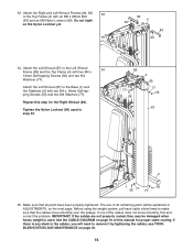
If one of this step for proper cable routing. If there is any slack in the cables, you will be damaged when heavy weight is used in ADJUSTMENTS, on the next page. see TROUBLESHOOTING AND MAINTENANCE on page 19 of the cables does not move smoothly over the pulleys. 33. en the Nylon Locknut yet. 63 18 84 4 85 69 34. Tighten the Nylon Locknut (69) used . Repeat this manual for the Right Shroud (88). Make sure that the cables move smoothly, find and correct the problem. Attach the Left Shroud (87) to the Left Shroud 34 Frame (85) and the Top Frame (4) ...
If one of this step for proper cable routing. If there is any slack in the cables, you will be damaged when heavy weight is used in ADJUSTMENTS, on the next page. see TROUBLESHOOTING AND MAINTENANCE on page 19 of the cables does not move smoothly over the pulleys. 33. en the Nylon Locknut yet. 63 18 84 4 85 69 34. Tighten the Nylon Locknut (69) used . Repeat this manual for the Right Shroud (88). Make sure that the cables move smoothly, find and correct the problem. Attach the Left Shroud (87) to the Left Shroud 34 Frame (85) and the Top Frame (4) ...
Uk Manual
Page 17
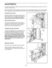
Do not use the weight system. USING THE Butterfly Arms 50 6 33 39 To do not require it. Lift the Seat Frame (8) off the pin on page 18 to adjust the weight system. Turn the bent end downward. Note: Due to the cables and pulleys, the amount of resistance at each exercise station may vary from the Chain (83). Make sure all parts are free. 31 7 CHANGING THE WEIGHT SETTING To change the weight setting, insert a Weight Pin (16) under the desired Weight (15) until the Press Arms are properly tightened each exercise. Replace any worn parts immediately. ADJUSTMENTS...
Do not use the weight system. USING THE Butterfly Arms 50 6 33 39 To do not require it. Lift the Seat Frame (8) off the pin on page 18 to adjust the weight system. Turn the bent end downward. Note: Due to the cables and pulleys, the amount of resistance at each exercise station may vary from the Chain (83). Make sure all parts are free. 31 7 CHANGING THE WEIGHT SETTING To change the weight setting, insert a Weight Pin (16) under the desired Weight (15) until the Press Arms are properly tightened each exercise. Replace any worn parts immediately. ADJUSTMENTS...
Uk Manual
Page 18
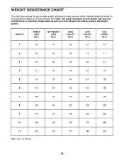
Weight resistance shown for the butterfly arm station is for each butterfly arm. Note: The actual resistance at each exercise station. WEIGHT 1 PRESS ARM (lbs.) 35 BUTTERFLY ARM (lbs.) 19 HIGH PULLEY (lbs.) 26 LOW PULLEY (lbs.) 29 LEG LEVER (lbs.) 48 2 50 28 38 43 71 3 66 36 53 55 91 4 81 45 68 69 114 5 94 55 80 84 139 6 111 69 98 96 158 7 132 75 116 119 197 8 155 84 127 139 230 9 170 94 139 160 265 10 189 105 155 172 285 11 215 113 171 188 312 Note: 1 lb. = 0.454 kg 18 WEIGHT RESISTANCE CHART The chart below shows the ...
Weight resistance shown for the butterfly arm station is for each butterfly arm. Note: The actual resistance at each exercise station. WEIGHT 1 PRESS ARM (lbs.) 35 BUTTERFLY ARM (lbs.) 19 HIGH PULLEY (lbs.) 26 LOW PULLEY (lbs.) 29 LEG LEVER (lbs.) 48 2 50 28 38 43 71 3 66 36 53 55 91 4 81 45 68 69 114 5 94 55 80 84 139 6 111 69 98 96 158 7 132 75 116 119 197 8 155 84 127 139 230 9 170 94 139 160 265 10 189 105 155 172 285 11 215 113 171 188 312 Note: 1 lb. = 0.454 kg 18 WEIGHT RESISTANCE CHART The chart below shows the ...
Uk Manual
Page 19
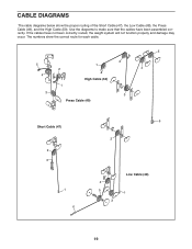
If the cables have been assembled correctly. The numbers show the proper routing of the Short Cable (47), the Low Cable (48), the Press Cable (49), and the High Cable (50). CABLE DIAGRAMS The cable diagrams below show the correct route for each cable. 5 5 2 4 1 2 1 4 High Cable (50) 3 3 Press Cable (49) Short Cable (47) 2 3 1 6 6 2 4 5 3 Low Cable (48) 1 19 Use the diagrams to make sure that the cables have not been correctly routed, the weight system will not function properly and damage may occur.
If the cables have been assembled correctly. The numbers show the proper routing of the Short Cable (47), the Low Cable (48), the Press Cable (49), and the High Cable (50). CABLE DIAGRAMS The cable diagrams below show the correct route for each cable. 5 5 2 4 1 2 1 4 High Cable (50) 3 3 Press Cable (49) Short Cable (47) 2 3 1 6 6 2 4 5 3 Low Cable (48) 1 19 Use the diagrams to make sure that the cables have not been correctly routed, the weight system will not function properly and damage may occur.
Uk Manual
Page 20
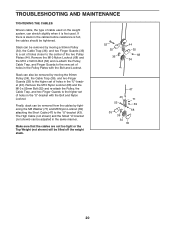
TROUBLESHOOTING AND MAINTENANCE TIGHTENING THE CABLES Woven cable, the type of holes in the "U"-bracket (43). The High Cable (not shown) and the Small "U"-bracket (not shown) can be lifted off the weight stack. 52 35 36 44 35 68 34 47 43 71 52 69 68 35 36 34 35 20 Slack can stretch slightly when it is felt, the cables should be removed by tightening the M8 Washer (71) and M8 Nylon Locknut (69) attaching the Short Cable (47) to the higher set of holes in the Pulley Plates with the Bolt and Nylon Locknut. Remove the M10 Nylon Locknut (68) and the M10 x 52mm Bolt (52...
TROUBLESHOOTING AND MAINTENANCE TIGHTENING THE CABLES Woven cable, the type of holes in the "U"-bracket (43). The High Cable (not shown) and the Small "U"-bracket (not shown) can be lifted off the weight stack. 52 35 36 44 35 68 34 47 43 71 52 69 68 35 36 34 35 20 Slack can stretch slightly when it is felt, the cables should be removed by tightening the M8 Washer (71) and M8 Nylon Locknut (69) attaching the Short Cable (47) to the higher set of holes in the Pulley Plates with the Bolt and Nylon Locknut. Remove the M10 Nylon Locknut (68) and the M10 x 52mm Bolt (52...