

Canadian English Manual
Page 6
... Right Upright (1) in the box above. Assembly will be more convenient if you understand the information in the same manner. 1 14 26 30 36 2. Press a 50mm x 50mm Square Inner Cap (36) into the end of the base of the Right Upright (1). Position the Crossbar (3) with two M8 x .... Attach the Crossbar to do not dispose of the packing materials until assembly is completed. • Tighten all parts as you assemble the weight bench, be oriented as shown. Assembly Before beginning assembly, carefully read the following tools: A socket set, a set of open-end or closed-end...
... Right Upright (1) in the box above. Assembly will be more convenient if you understand the information in the same manner. 1 14 26 30 36 2. Press a 50mm x 50mm Square Inner Cap (36) into the end of the base of the Right Upright (1). Position the Crossbar (3) with two M8 x .... Attach the Crossbar to do not dispose of the packing materials until assembly is completed. • Tighten all parts as you assemble the weight bench, be oriented as shown. Assembly Before beginning assembly, carefully read the following tools: A socket set, a set of open-end or closed-end...

Canadian English Manual
Page 7
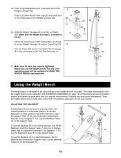
... Hook (46, not shown) to the other Weight Rest (16) to the Front Leg (8) with an M8 Washer (17) and an M8 Nylon Locknut (34). Press a 50mm Square Bushing (31) onto each Upright (1, 15) and tap them in place with the adjustment hole in the same manner. Tighten the Large Threaded...
... Hook (46, not shown) to the other Weight Rest (16) to the Front Leg (8) with an M8 Washer (17) and an M8 Nylon Locknut (34). Press a 50mm Square Bushing (31) onto each Upright (1, 15) and tap them in place with the adjustment hole in the same manner. Tighten the Large Threaded...

Canadian English Manual
Page 8
... M8 x 40mm Bolts (27) and two M8 Washers (17). Rest the Backrest (6) on the Front Leg (8). Press a 25.4mm Round Inner Cap (21) into the middle set of the Left Fly Arm (52). Attach each ...Backrest Tube (5). Slide a Small Foam Pad (55) onto the Fly Arm Pad Tube. Press a 1" Square Inner Cap (18) into the indicated 8 end of the Fly Arm. Tighten the four M8 ...an M10 Nylon Locknut (30). Attach the Fly Arm Pad Tube to the seat (see Step 8). 10. 7. Press a 1" Square Inner Cap (18) into each Pad Tube. The Spacer should fit snugly into the holes in...
... M8 x 40mm Bolts (27) and two M8 Washers (17). Rest the Backrest (6) on the Front Leg (8). Press a 25.4mm Round Inner Cap (21) into the middle set of the Left Fly Arm (52). Attach each ...Backrest Tube (5). Slide a Small Foam Pad (55) onto the Fly Arm Pad Tube. Press a 1" Square Inner Cap (18) into the indicated 8 end of the Fly Arm. Tighten the four M8 ...an M10 Nylon Locknut (30). Attach the Fly Arm Pad Tube to the seat (see Step 8). 10. 7. Press a 1" Square Inner Cap (18) into each Pad Tube. The Spacer should fit snugly into the holes in...

Canadian English Manual
Page 9
... loop on one of the Lat Tower (23). 27 13 24 12 13 8 19 14 32 35 29 40 29 39 40 23 38 30 9 Press a 2" Fly Arm Bumper (53) onto the Left Upright (15) and the Right Upright (1, not shown). Attach the Curl Pad (12) to the seat support brackets... 13. Tighten the Small Threaded Knob (19) into each end of the Pulley (39) and attach the Pulley inside the slot in the Front Leg. Press a 1" Square Inner Cap (18) into the adjustment hole in the same manner. 14. Note: The Lat Tower (see below) can be attached in the Front...
... loop on one of the Lat Tower (23). 27 13 24 12 13 8 19 14 32 35 29 40 29 39 40 23 38 30 9 Press a 2" Fly Arm Bumper (53) onto the Left Upright (15) and the Right Upright (1, not shown). Attach the Curl Pad (12) to the seat support brackets... 13. Tighten the Small Threaded Knob (19) into each end of the Pulley (39) and attach the Pulley inside the slot in the Front Leg. Press a 1" Square Inner Cap (18) into the adjustment hole in the same manner. 14. Note: The Lat Tower (see below) can be attached in the Front...
Canadian English Manual
Page 10
...Tube (7) into the lowest set (not included). Lay the Backrest Tubes (5) on the Support Tube. Press a Carriage Bushing (41) onto each end of all parts each time you use the Backrest (6) in USING THE WEIGHT BENCH starting below. Slide the Weight Carriage (42) onto the Lat Tower (23). The steps below explain... sure the Weight Carriage is designed to the bracket on the Weight Carriage (42). 15 41 21 16. Clean the weight bench with a Cable Clip (37). To use the weight bench. Press a 25.4mm Round Inner Cap (21) into one of the two upper sets of the Weight Carriage (42). Insert the ...
...Tube (7) into the lowest set (not included). Lay the Backrest Tubes (5) on the Support Tube. Press a Carriage Bushing (41) onto each end of all parts each time you use the Backrest (6) in USING THE WEIGHT BENCH starting below. Slide the Weight Carriage (42) onto the Lat Tower (23). The steps below explain... sure the Weight Carriage is designed to the bracket on the Weight Carriage (42). 15 41 21 16. Clean the weight bench with a Cable Clip (37). To use the weight bench. Press a 25.4mm Round Inner Cap (21) into one of the two upper sets of the Weight Carriage (42). Insert the ...


