
User Guide
Page 7
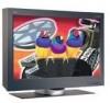
Hardware setup This chapter describes the following: • The location of the controls, switches, and connectors. • The procedure for setting up the display. Locations Front view Monitor screen Serial number label OSD control Brightness control Power switch Base stand Rear view DC-IN connector Video connector Security keyhole Power light (Power on/Standby) VESA wall mount holes Connector cover Stand rear cover Cable hook Cable clamp ViewSonic VP2290b 4
Hardware setup This chapter describes the following: • The location of the controls, switches, and connectors. • The procedure for setting up the display. Locations Front view Monitor screen Serial number label OSD control Brightness control Power switch Base stand Rear view DC-IN connector Video connector Security keyhole Power light (Power on/Standby) VESA wall mount holes Connector cover Stand rear cover Cable hook Cable clamp ViewSonic VP2290b 4

User Guide
Page 31
...provided for test purposes only) 7 8 9 10 11 12 13 ViewSonic VP2290b 28 Detailed timing information on the application requirements and the capability of the monitor is provided to 25Hz 1 2 3 VP2290b-2(for 4stripe) / VP2290b-3 modes Single input(13Hz), quad input(title - 41Hz) & ...quad input(stripe - 41Hz) 6 VP2290b-3 only modes Single input (24Hz)*, quad input (tile - 48Hz...
...provided for test purposes only) 7 8 9 10 11 12 13 ViewSonic VP2290b 28 Detailed timing information on the application requirements and the capability of the monitor is provided to 25Hz 1 2 3 VP2290b-2(for 4stripe) / VP2290b-3 modes Single input(13Hz), quad input(title - 41Hz) & ...quad input(stripe - 41Hz) 6 VP2290b-3 only modes Single input (24Hz)*, quad input (tile - 48Hz...


