User Guide English
Page 1
VS18518 P/N: VB-CAM-201 VB-CAM-201 User Guide IMPORTANT: Please read this User Guide will describe your limited coverage from ViewSonic® Corporation, which is also found on installing and using the Regional selection box in a safe manner, as well as registering your product in the upper right corner of our website. Model No. Warranty information contained in this User Guide to obtain important information on our web site at http://www.viewsonic.com in English, or in specific languages using your product for future service.
VS18518 P/N: VB-CAM-201 VB-CAM-201 User Guide IMPORTANT: Please read this User Guide will describe your limited coverage from ViewSonic® Corporation, which is also found on installing and using the Regional selection box in a safe manner, as well as registering your product in the upper right corner of our website. Model No. Warranty information contained in this User Guide to obtain important information on our web site at http://www.viewsonic.com in English, or in specific languages using your product for future service.

User Guide English
Page 3
... place the product on a flat, stable surface. • Avoid contacting any liquids, gas, or corrosive materials with the shell of the product. • This product has no parts which can be repaired by warranty. • Electromagnetic fields at specific frequencies may affect the image of machine. 3 Any damage caused by the user's own disassembly is not covered by the...
... place the product on a flat, stable surface. • Avoid contacting any liquids, gas, or corrosive materials with the shell of the product. • This product has no parts which can be repaired by warranty. • Electromagnetic fields at specific frequencies may affect the image of machine. 3 Any damage caused by the user's own disassembly is not covered by the...
User Guide English
Page 4
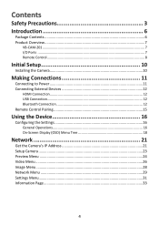
......6 Product Overview...7 VB-CAM-201...7 I/O Ports ...7 Remote Control...8 Initial Setup 10 Installing the Camera 10 Making Connections 11 Connecting to Power 11 Connecting External Devices 12 HDMI Connection 12 USB Connection...12 Bluetooth Connection 12 Remote Control Pairing 15 Using the Device 16 Configuring the Settings 16 General Operations 16 On-Screen Display (OSD) Menu Tree 18 Network 21 Get the Camera's IP Address 21 Setup Camera...23 Preview Menu...24 Video Menu...26 Image Menu...28 Network Menu...29 Settings Menu...31 Information Page...
......6 Product Overview...7 VB-CAM-201...7 I/O Ports ...7 Remote Control...8 Initial Setup 10 Installing the Camera 10 Making Connections 11 Connecting to Power 11 Connecting External Devices 12 HDMI Connection 12 USB Connection...12 Bluetooth Connection 12 Remote Control Pairing 15 Using the Device 16 Configuring the Settings 16 General Operations 16 On-Screen Display (OSD) Menu Tree 18 Network 21 Get the Camera's IP Address 21 Setup Camera...23 Preview Menu...24 Video Menu...26 Image Menu...28 Network Menu...29 Settings Menu...31 Information Page...
User Guide English
Page 7
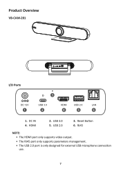
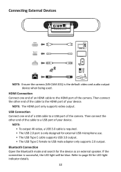
USB 2.0 3. HDMI 2. USB 3.0 5. RJ45 NOTE: • The HDMI port only supports video output. • The RJ45 port only supports parameters management. • The USB 2.0 port is only designed for external USB microphone connection use. 7 DC IN 4. Reset Button 6. Product Overview VB-CAM-201 DC 12V USB 3.0 HDMI USB 2.0 LAN I/O Ports 3 DC 12V 1 USB 3.0 2 HDMI USB 2.0 LAN 4 5 6 1.
USB 2.0 3. HDMI 2. USB 3.0 5. RJ45 NOTE: • The HDMI port only supports video output. • The RJ45 port only supports parameters management. • The USB 2.0 port is only designed for external USB microphone connection use. 7 DC IN 4. Reset Button 6. Product Overview VB-CAM-201 DC 12V USB 3.0 HDMI USB 2.0 LAN I/O Ports 3 DC 12V 1 USB 3.0 2 HDMI USB 2.0 LAN 4 5 6 1.

User Guide English
Page 8
Menu Control/Camera moving direction. Audio volume control. After pressing, the camera will automatically track the participants. short press to set Preset 2; Enter/Exit the OSD menu. short press to return to home position. Disable/Enable the microphone. Long press to call interface1. Confirm selection/Camera returns to Normal mode. Long press to join the meeting1. Long press to set Preset 1; Disable/Enable the...
Menu Control/Camera moving direction. Audio volume control. After pressing, the camera will automatically track the participants. short press to set Preset 2; Enter/Exit the OSD menu. short press to return to home position. Disable/Enable the microphone. Long press to call interface1. Confirm selection/Camera returns to Normal mode. Long press to join the meeting1. Long press to set Preset 1; Disable/Enable the...
User Guide English
Page 12
... USB Type C cable supports USB 3.0 output. • The USB Type C female to the HDMI port of the cable to USB male adapter only supports 2.0 output. If the connection is the default video and audio output device when being used. Refer to a USB port of your device. Connecting External Devices HDMI Type-C DC 12V USB 3.0 HDMI USB 2.0 LAN LAN NOTE: Ensure the camera (VB-CAM-201) is successful, the LED light will be blue. USB Connection Connect one end of an HDMI cable to a USB port of...
... USB Type C cable supports USB 3.0 output. • The USB Type C female to the HDMI port of the cable to USB male adapter only supports 2.0 output. If the connection is the default video and audio output device when being used. Refer to a USB port of your device. Connecting External Devices HDMI Type-C DC 12V USB 3.0 HDMI USB 2.0 LAN LAN NOTE: Ensure the camera (VB-CAM-201) is successful, the LED light will be blue. USB Connection Connect one end of an HDMI cable to a USB port of...
User Guide English
Page 13
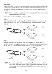
... a minimum level and cannot be adjusted. The user can automatically connect to VB-AUD-201 and has a connection capacity of two. Host Mode Under host mode, VB-CAM-201 can switch the Host mode in BT Host Mode setting in the OSD Menu or via Remote Control. Host 1: Under Host 1, the audio is only output from VB-AUD-201 and the speaker on VBCAM-201 is limited to know the LED light difference between Host 1 and...
... a minimum level and cannot be adjusted. The user can automatically connect to VB-AUD-201 and has a connection capacity of two. Host Mode Under host mode, VB-CAM-201 can switch the Host mode in BT Host Mode setting in the OSD Menu or via Remote Control. Host 1: Under Host 1, the audio is only output from VB-AUD-201 and the speaker on VBCAM-201 is limited to know the LED light difference between Host 1 and...
User Guide English
Page 15
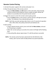
After which, the pairing mode will switch to enter the remote control pairing mode: ͫ Press the Reset button on . 2. Clear the paired status of operation time. Trigger the camera to blue. NOTE: The remote control has been paired with the VB-CAM-201 at the same time, keep pressing until the pairing is successful. Connect the power supply to the camera and power it can be flashing blue. ͫ If...
After which, the pairing mode will switch to enter the remote control pairing mode: ͫ Press the Reset button on . 2. Clear the paired status of operation time. Trigger the camera to blue. NOTE: The remote control has been paired with the VB-CAM-201 at the same time, keep pressing until the pairing is successful. Connect the power supply to the camera and power it can be flashing blue. ͫ If...
User Guide English
Page 17
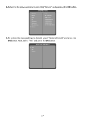
Return to default, select "Restore Default" and press the OK button. To restore the menu settings to the previous menu by selecting "Return" and pressing the OK button. Next, select "Yes" and press the OK button. 3. INFORMATION Version Model Date IP Gateway Netmask MacAddress Return 1.0.0 VB-CAM-201 2021-12-31 192.168.000.22 192.168.000.1 355.355.355.0 9C:1F:32:8E:20:03 4. RESTORE DEFAULT Yes No Return 17
Return to default, select "Restore Default" and press the OK button. To restore the menu settings to the previous menu by selecting "Return" and pressing the OK button. Next, select "Yes" and press the OK button. 3. INFORMATION Version Model Date IP Gateway Netmask MacAddress Return 1.0.0 VB-CAM-201 2021-12-31 192.168.000.22 192.168.000.1 355.355.355.0 9C:1F:32:8E:20:03 4. RESTORE DEFAULT Yes No Return 17

User Guide English
Page 21
... Address The camera's factory default IP address is set as Fixed IP address. Connect to a Computer 1 2 LAN LAN Connect the camera to the Ethernet interface of the computer (LAN port). 3. Connect the other end of a CAT5/5e/6 network cable to the camera automatically. To check this IP address, you can use the remote control to open the menu and find the intranet setting in the INFORMATION...
... Address The camera's factory default IP address is set as Fixed IP address. Connect to a Computer 1 2 LAN LAN Connect the camera to the Ethernet interface of the computer (LAN port). 3. Connect the other end of a CAT5/5e/6 network cable to the camera automatically. To check this IP address, you can use the remote control to open the menu and find the intranet setting in the INFORMATION...

User Guide English
Page 24
... in /out "zoom speed". The camera will adjust the Pan, Tilt, and Zoom to your desired position. 2. Click the Set button to call presets • Pan, Tilt, and On-Screen Display (OSD) menu control Zoom Manually adjust the zoom of the camera. Input the preset number you want to save this position. 3. Click the Call button to this position. Key in the number you want to assign to recall the...
... in /out "zoom speed". The camera will adjust the Pan, Tilt, and Zoom to your desired position. 2. Click the Set button to call presets • Pan, Tilt, and On-Screen Display (OSD) menu control Zoom Manually adjust the zoom of the camera. Input the preset number you want to save this position. 3. Click the Call button to this position. Key in the number you want to assign to recall the...

User Guide English
Page 28
.... Apply as default Click this button to set the Brightness, Saturation, Contrast, and Sharpness back to increase/decrease the clarity of the video image. Sharpness Adjust these values to suit the ambient conditions. NOTE: A higher sharpness value increases the noise in the video image. Adjust these values to the default value. 28 Contrast Contrast of the video image. Saturation Saturation of the video image. Image Menu Brightness Brightness of detail in the video image.
.... Apply as default Click this button to set the Brightness, Saturation, Contrast, and Sharpness back to increase/decrease the clarity of the video image. Sharpness Adjust these values to suit the ambient conditions. NOTE: A higher sharpness value increases the noise in the video image. Adjust these values to the default value. 28 Contrast Contrast of the video image. Saturation Saturation of the video image. Image Menu Brightness Brightness of detail in the video image.

User Guide English
Page 30
... number HTTP port for the HTTP protocol is 80. NOTE: When changing the above network settings, don't forget to click the Apply button to use the new setting(s), or click the Cancel button to abort the new setting(s) and use the current setting(s). 30 NOTE: Username and password are required for the RTSP transmission is not occupied by another device. DNS address Manually...
... number HTTP port for the HTTP protocol is 80. NOTE: When changing the above network settings, don't forget to click the Apply button to use the new setting(s), or click the Cancel button to abort the new setting(s) and use the current setting(s). 30 NOTE: Username and password are required for the RTSP transmission is not occupied by another device. DNS address Manually...

User Guide English
Page 34
... Digital Zoom, Pan/Tilt ± 15° MPT + EPTZ 2D & 3D Digital Noise Reduction ≥ 55dB Support Audio Item Full Frequency Speaker Microphone Array Specifications 96 dB SPL in the case of 0.5 meters Beamforming microphone, pick up distance up to 6 meters USB Features Item Connection Type Video Compression USB Audio USB Communication Protocol UVC PTZ Control Specifications USB 3.0, downward compatible with USB 2.0 YUY2 / MJPG / H.264 32K sampling rate, support UAC 2.0 UVC 1.1~1.5 Support Input...
... Digital Zoom, Pan/Tilt ± 15° MPT + EPTZ 2D & 3D Digital Noise Reduction ≥ 55dB Support Audio Item Full Frequency Speaker Microphone Array Specifications 96 dB SPL in the case of 0.5 meters Beamforming microphone, pick up distance up to 6 meters USB Features Item Connection Type Video Compression USB Audio USB Communication Protocol UVC PTZ Control Specifications USB 3.0, downward compatible with USB 2.0 YUY2 / MJPG / H.264 32K sampling rate, support UAC 2.0 UVC 1.1~1.5 Support Input...

User Guide English
Page 38
Troubleshooting Problem or Issue No power The video image displayed by the camera is shaking Possible Solutions • Make sure you have turned on the device by pressing the Power button on the remote control. • Make sure the power cord is properly and securely connected to the device and power outlet. • Plug another electrical device into the power outlet to verify that the outlet is supplying power. • Ensure the camera is securely installed and stable. • Check for any nearby equipment that may be giving off vibrations. 38
Troubleshooting Problem or Issue No power The video image displayed by the camera is shaking Possible Solutions • Make sure you have turned on the device by pressing the Power button on the remote control. • Make sure the power cord is properly and securely connected to the device and power outlet. • Plug another electrical device into the power outlet to verify that the outlet is supplying power. • Ensure the camera is securely installed and stable. • Check for any nearby equipment that may be giving off vibrations. 38

User Guide English
Page 39
... bright objects (e.g., sunlight), and unstable light conditions. • Do not use the camera around facilities that can transmit high-power radio waves (e.g., television station). Maintenance General Precautions • Make sure the camera is turned off and the power cable is unplugged from the power outlet if it will not be used for damage resulting from use of any ammonia or alcohol-based...
... bright objects (e.g., sunlight), and unstable light conditions. • Do not use the camera around facilities that can transmit high-power radio waves (e.g., television station). Maintenance General Precautions • Make sure the camera is turned off and the power cable is unplugged from the power outlet if it will not be used for damage resulting from use of any ammonia or alcohol-based...
User Guide English
Page 40
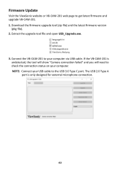
Firmware Update Visit the ViewSonic website or VB-CAM-201 web page to check the connection status on your computer via USB cable. Extract the upgrade tool file and open USB_Upgrade.exe. 3. If the VB-CAM-201 is only designed for external microphone connection. 40 Connect the VB-CAM-201 to the USB 3.0 Type C port. The USB 2.0 Type A port is undetected, the tool will show "Camera connection failed" and you will need to get latest firmware and upgrade VB-CAM-201. 1. NOTE...
Firmware Update Visit the ViewSonic website or VB-CAM-201 web page to check the connection status on your computer via USB cable. Extract the upgrade tool file and open USB_Upgrade.exe. 3. If the VB-CAM-201 is only designed for external microphone connection. 40 Connect the VB-CAM-201 to the USB 3.0 Type C port. The USB 2.0 Type A port is undetected, the tool will show "Camera connection failed" and you will need to get latest firmware and upgrade VB-CAM-201. 1. NOTE...

User Guide English
Page 52
... on your sole remedy, repair or replace the product with the product or installed by ViewSonic® ͫ Damage to be free from the date of the first consumer purchase. Limited Warranty ViewSonic® Display What the warranty covers: ViewSonic® warrants its sole option, and as your country of purchase, for all parts including the light source and for all labor...
... on your sole remedy, repair or replace the product with the product or installed by ViewSonic® ͫ Damage to be free from the date of the first consumer purchase. Limited Warranty ViewSonic® Display What the warranty covers: ViewSonic® warrants its sole option, and as your country of purchase, for all parts including the light source and for all labor...
User Guide English
Page 53
... nearest ViewSonic® service center, contact ViewSonic®. • Software or data loss occurring during repair or replacement. • Any damage of the product due to shipment. • Causes external to the product, such as electric power fluctuations or failure. • Use of supplies or parts not meeting ViewSonic's specifications. • Failure of owner to perform periodic product maintenance as stated in the User Guide...
... nearest ViewSonic® service center, contact ViewSonic®. • Software or data loss occurring during repair or replacement. • Any damage of the product due to shipment. • Causes external to the product, such as electric power fluctuations or failure. • Use of supplies or parts not meeting ViewSonic's specifications. • Failure of owner to perform periodic product maintenance as stated in the User Guide...
User Guide English
Page 55
..., under normal use, during the warranty period, ViewSonic® will, at its products to follow instructions supplied with a like product. What the warranty excludes and does not cover: • Any product on which the serial number has been defaced, modified or removed. • Damage, deterioration, or malfunction resulting from the date of time. • Removal, installation, insurance, and set-up service charges...
..., under normal use, during the warranty period, ViewSonic® will, at its products to follow instructions supplied with a like product. What the warranty excludes and does not cover: • Any product on which the serial number has been defaced, modified or removed. • Damage, deterioration, or malfunction resulting from the date of time. • Removal, installation, insurance, and set-up service charges...


