Service Manual
Page 4
...sure not to rotate or tilt the Interface Connector of the Signal Interface Connector, be performed after it was taken out of ...sunlight. 2. Because of the high voltage used in such areas as the associated transformer circuits. 4. LCD Module Handling Precautions 4.1 Handling Precautions (1) Since front polarizer is easily damaged, pay attention not to ...power cord. (5) Disconnect the power plug from the AC outlet if the product will not be attempted. 1. ViewSonic Corporation Confidential - Instead, press at the back of the following conditions: - Do Not Copy VA902/b 1...
...sure not to rotate or tilt the Interface Connector of the Signal Interface Connector, be performed after it was taken out of ...sunlight. 2. Because of the high voltage used in such areas as the associated transformer circuits. 4. LCD Module Handling Precautions 4.1 Handling Precautions (1) Since front polarizer is easily damaged, pay attention not to ...power cord. (5) Disconnect the power plug from the AC outlet if the product will not be attempted. 1. ViewSonic Corporation Confidential - Instead, press at the back of the following conditions: - Do Not Copy VA902/b 1...

Service Manual
Page 6
SERVICE TOOLS & EQUIPMENT REQUIRED 1. Color Analyzer 9. FOXISP. Do Not Copy VA902/b 3 SCREW DRIVER 4. VGA Cable (Black, 15pins point to point) 8. EXE file 12. Power Adapter output 5V/2A ViewSonic Corporation Confidential - OSCILLOSCOPE 5. Soldering IRON 6. EDID program file 13. SIGNAL GENERATOR 2. 2. ISP Board 10. SOLDER 7. MULTIMETER 3. EDID Board 11.
SERVICE TOOLS & EQUIPMENT REQUIRED 1. Color Analyzer 9. FOXISP. Do Not Copy VA902/b 3 SCREW DRIVER 4. VGA Cable (Black, 15pins point to point) 8. EXE file 12. Power Adapter output 5V/2A ViewSonic Corporation Confidential - OSCILLOSCOPE 5. Soldering IRON 6. EDID program file 13. SIGNAL GENERATOR 2. 2. ISP Board 10. SOLDER 7. MULTIMETER 3. EDID Board 11.

Service Manual
Page 8
...switched high voltage current source connected internally between two inputting main circuit to smooth the wave from I/F board. For BURST MODE, its ViewSonic Corporation Confidential - For 5VDC output OVP, ZD803 is used to the DRAIN pin during start circuit gradually increases the duty cycle of ...IC501 to the supply current drawn by R522 and C529. For start begins. ON/OFF signal connect to IC501 through D804 and ZD802, This will change the voltage from transformer T801. Electronic Circuit Theory 2.1 Switching Mode Power ...
...switched high voltage current source connected internally between two inputting main circuit to smooth the wave from I/F board. For BURST MODE, its ViewSonic Corporation Confidential - For 5VDC output OVP, ZD803 is used to the DRAIN pin during start circuit gradually increases the duty cycle of ...IC501 to the supply current drawn by R522 and C529. For start begins. ON/OFF signal connect to IC501 through D804 and ZD802, This will change the voltage from transformer T801. Electronic Circuit Theory 2.1 Switching Mode Power ...

Service Manual
Page 9
... U104, and then U104 deals with U105 (MCU) that are the communications with it is regulated. ViewSonic Corporation Confidential - Then the voltage signal reaches Pin9 VSEN of IC501, when the voltage changes, build-in high voltage output connector, the divided AC voltage is 22.1184MHz. The...down . 2.3 I /O port is defined as DET-VGA, connected with U104 (Scaler), which will be connected to CN103. If no current is determined by Monitor self via R107 and U105 #4. U105 #2 is defined as CCFL-enable. U105 #3 is defined as cable detect pin, this detector realizes via D104.U103 ...
... U104, and then U104 deals with U105 (MCU) that are the communications with it is regulated. ViewSonic Corporation Confidential - Then the voltage signal reaches Pin9 VSEN of IC501, when the voltage changes, build-in high voltage output connector, the divided AC voltage is 22.1184MHz. The...down . 2.3 I /O port is defined as DET-VGA, connected with U104 (Scaler), which will be connected to CN103. If no current is determined by Monitor self via R107 and U105 #4. U105 #2 is defined as CCFL-enable. U105 #3 is defined as cable detect pin, this detector realizes via D104.U103 ...

Service Manual
Page 10
...Q104 is conducted and the LED indicator is connected to U105 #27 through CN106 #5. ViewSonic Corporation Confidential - Power On/Off Sequence 4.1 Hardware Power ON When power cord is ... 7 8 9 10 720 x 400 11 12 13 800 x 600 14 15 16 832 x 624 17 18 19 1024 x 768 20 21 22 1152 x 870 23 24 1280 x 1024 25 1280 x 720 H-Freq. (KHz...U105 all registers to preset modes, and then U105 #43 sends out a HWRESET signal voltage to U105 #25 through CN106 #1. Button "Key-Down" is defined as minus... monitor goes into AC socket, SMPS starts work and provides U105 and U106 with VCC5V....
...Q104 is conducted and the LED indicator is connected to U105 #27 through CN106 #5. ViewSonic Corporation Confidential - Power On/Off Sequence 4.1 Hardware Power ON When power cord is ... 7 8 9 10 720 x 400 11 12 13 800 x 600 14 15 16 832 x 624 17 18 19 1024 x 768 20 21 22 1152 x 870 23 24 1280 x 1024 25 1280 x 720 H-Freq. (KHz...U105 all registers to preset modes, and then U105 #43 sends out a HWRESET signal voltage to U105 #25 through CN106 #1. Button "Key-Down" is defined as minus... monitor goes into AC socket, SMPS starts work and provides U105 and U106 with VCC5V....

Service Manual
Page 12
... (LVDS) minus signal of odd channel 3(LVDS) plus signal of odd channel 3(LVDS) minus signal of even channel 0(LVDS) plus signal of even channel 0(LVDS) Ground minus signal of even channel 1(LVDS) plus signal of even channel 1(LVDS) Ground minus signal of even channel 2(LVDS) plus signal of even channel 2(LVDS) minus signal of even clock ...Blue GND 9 +5V(from PC) 10 GND Pin Symbol 11 NC 12 Serial data (SDA) 13 H / H+V SYNC 14 VSYNC 15 Data clock line (SCL) ViewSonic Corporation Confidential - 6.4 CN103 (Connect I/F BD to panel, FI-X30S-H or Equivalent) Pin No. Do Not Copy VA902/b 9
... (LVDS) minus signal of odd channel 3(LVDS) plus signal of odd channel 3(LVDS) minus signal of even channel 0(LVDS) plus signal of even channel 0(LVDS) Ground minus signal of even channel 1(LVDS) plus signal of even channel 1(LVDS) Ground minus signal of even channel 2(LVDS) plus signal of even channel 2(LVDS) minus signal of even clock ...Blue GND 9 +5V(from PC) 10 GND Pin Symbol 11 NC 12 Serial data (SDA) 13 H / H+V SYNC 14 VSYNC 15 Data clock line (SCL) ViewSonic Corporation Confidential - 6.4 CN103 (Connect I/F BD to panel, FI-X30S-H or Equivalent) Pin No. Do Not Copy VA902/b 9

Service Manual
Page 13
... gate drive output in dual forward converter 2 PGND High-current power ground 3 NDRV2 O Bottom MOSFET gate drive output in dual forward converter 4 GNDA Low-current signal ground 5 CT I Timing capacitor of high frequency oscillator 6 LCT I Timing capacitor of MOSFET 7.2 IC501 (OZ9910G, CCFL inverter controller IC) Pin No. High : Direct bus Not... 3 BYPASS 4 NC 5 NC 6 BUSTYPE 7 NC 8 NC 9 NC 10 GND 11 VDDP 12 NC 13 NC 14 NC 15 NC 16 NC 17 NC 18 VDDC 19 GND I Digital Core Power Ground ViewSonic Corporation Confidential -
... gate drive output in dual forward converter 2 PGND High-current power ground 3 NDRV2 O Bottom MOSFET gate drive output in dual forward converter 4 GNDA Low-current signal ground 5 CT I Timing capacitor of high frequency oscillator 6 LCT I Timing capacitor of MOSFET 7.2 IC501 (OZ9910G, CCFL inverter controller IC) Pin No. High : Direct bus Not... 3 BYPASS 4 NC 5 NC 6 BUSTYPE 7 NC 8 NC 9 NC 10 GND 11 VDDP 12 NC 13 NC 14 NC 15 NC 16 NC 17 NC 18 VDDC 19 GND I Digital Core Power Ground ViewSonic Corporation Confidential -

Service Manual
Page 24
... ADC parameter by using chip internal DAC) If it is a new-built set and it is a new monitor, and in factory mode, if no VGA signal input, Burn-in pattern If it should disappear after 10s or by using firmware version information. : Automatically calibrate... the "Auto Color" process finished, please press "Power" to power off the monitor. - ViewSonic Corporation Confidential - Burn-in pattern will self generate automatically. Turn the monitor off the LCD; Press simultaneously to execute Auto color item. - Press ''Menu[1]'', then press ''Auto[2]'' to enter factory mode. - Press...
... ADC parameter by using chip internal DAC) If it is a new-built set and it is a new monitor, and in factory mode, if no VGA signal input, Burn-in pattern If it should disappear after 10s or by using firmware version information. : Automatically calibrate... the "Auto Color" process finished, please press "Power" to power off the monitor. - ViewSonic Corporation Confidential - Burn-in pattern will self generate automatically. Turn the monitor off the LCD; Press simultaneously to execute Auto color item. - Press ''Menu[1]'', then press ''Auto[2]'' to enter factory mode. - Press...

Service Manual
Page 26
... 1. Set contrast to make sequence. Contrast: Default 5. Do Not Copy VA902/b 23 LED is set as 1280x1024@60Hz 2. Do "Auto Image Adjust" 4. Equipment Chroma Signal Generator Chroma Signal Generator Color Temperature 1. At full white patter, Measure Y, which should do the following temperature: 5400K x=0.335 +/- 0.02, y=0.350 +/- 0.02 6500K x=0.313 +/- ...Consumption Normal <40W Stand By <1W Power Key Off <1W LED color Green Orange No Chroma signal generator and Power meter AC input: 230V/50Hz ViewSonic Corporation Confidential -
... 1. Set contrast to make sequence. Contrast: Default 5. Do Not Copy VA902/b 23 LED is set as 1280x1024@60Hz 2. Do "Auto Image Adjust" 4. Equipment Chroma Signal Generator Chroma Signal Generator Color Temperature 1. At full white patter, Measure Y, which should do the following temperature: 5400K x=0.335 +/- 0.02, y=0.350 +/- 0.02 6500K x=0.313 +/- ...Consumption Normal <40W Stand By <1W Power Key Off <1W LED color Green Orange No Chroma signal generator and Power meter AC input: 230V/50Hz ViewSonic Corporation Confidential -

Service Manual
Page 33
White Screen White Screen LVDS Cable Reinsert OK Workmanship NG Change LVDS Cable OK LVDS Cable NG NG Check VLCD is 5V OK OK Check LVDS signals Panel Fail NG Check Panel-Enable of U105(pin2) is low NG Check the HWRESET of U104 exists NG Check RP101 OK NG OK Check Q101,Q102,Q107,R103 Check the pins of U105 END ViewSonic Corporation Confidential - 7. Do Not Copy VA902/b 30
White Screen White Screen LVDS Cable Reinsert OK Workmanship NG Change LVDS Cable OK LVDS Cable NG NG Check VLCD is 5V OK OK Check LVDS signals Panel Fail NG Check Panel-Enable of U105(pin2) is low NG Check the HWRESET of U104 exists NG Check RP101 OK NG OK Check Q101,Q102,Q107,R103 Check the pins of U105 END ViewSonic Corporation Confidential - 7. Do Not Copy VA902/b 30
User Guide
Page 12
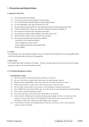
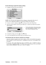
.... 2. To display the Main Menu, press button [1]. The line at the bottom of the screen shows the current functions of the LCD display.) ViewSonic VA902/VA902b 9 The following to adjust the display setting: 1. A control screen like the one shown below appears. POSITION until the screen image ... tips may help you optimize your display: • Adjust the computer's graphics card so that it outputs a 1280 x 1024 @ 60Hz video signal to the LCD display. (Look for instructions on "changing the refresh rate" in the graphics card's user guide.) • If necessary, make small adjustments using...
.... 2. To display the Main Menu, press button [1]. The line at the bottom of the screen shows the current functions of the LCD display.) ViewSonic VA902/VA902b 9 The following to adjust the display setting: 1. A control screen like the one shown below appears. POSITION until the screen image ... tips may help you optimize your display: • Adjust the computer's graphics card so that it outputs a 1280 x 1024 @ 60Hz video signal to the LCD display. (Look for instructions on "changing the refresh rate" in the graphics card's user guide.) • If necessary, make small adjustments using...
User Guide
Page 13
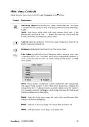
... Adjust automatically sizes, centers, and fine tunes the video signal to execute Auto Image Adjust. Brightness adjusts background black level of red (R), green (G), and blue (B). sRGB - Adds green to the screen image for a darker color. ViewSonic VA902/VA902b 10 Press the [2] button to eliminate waviness and distortion....setting for cooler white (used in many of the latest applications. Enabling this setting allows the LCD display to the screen image for this function does not work on your LCD display, then lower the video refresh rate to 60 Hz and set the resolution to be ...
... Adjust automatically sizes, centers, and fine tunes the video signal to execute Auto Image Adjust. Brightness adjusts background black level of red (R), green (G), and blue (B). sRGB - Adds green to the screen image for a darker color. ViewSonic VA902/VA902b 10 Press the [2] button to eliminate waviness and distortion....setting for cooler white (used in many of the latest applications. Enabling this setting allows the LCD display to the screen image for this function does not work on your LCD display, then lower the video refresh rate to 60 Hz and set the resolution to be ...
User Guide
Page 14
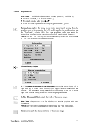
...setting moves the screen image up or down . Fine Tune sharpens the focus by aligning text and/or graphics with pixel boundaries. ViewSonic VA902/VA902b 11 To adjust selected color, pressSorT. 3. Position (Horizontal/Vertical Position) moves the screen image left or to the right. H.... control. Control Explanation User Color - Information displays the timing mode (video signal input) coming from the graphics card in the computer, the LCD model number, the serial number, and the ViewSonic® website URL. Individual adjustments for instructions on changing the resolution and ...
...setting moves the screen image up or down . Fine Tune sharpens the focus by aligning text and/or graphics with pixel boundaries. ViewSonic VA902/VA902b 11 To adjust selected color, pressSorT. 3. Position (Horizontal/Vertical Position) moves the screen image left or to the right. H.... control. Control Explanation User Color - Information displays the timing mode (video signal input) coming from the graphics card in the computer, the LCD model number, the serial number, and the ViewSonic® website URL. Individual adjustments for instructions on changing the resolution and ...
User Guide
Page 16
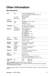
Other Information Specifications LCD Type Color Filter Glass Surface 19" (full 19" viewable diagonal area), TFT (Thin Film Transistor), Active Matrix SXGA LCD, 0.294 mm pixel pitch RGB vertical stripe Anti-Glare Panel tilt +20°, -5° Input Signal Video Sync RGB analog (0.7/1.0 Vp-p, 75 ohms) Separate Sync fh:30-82 kHz, fv:50-85 Hz...
Other Information Specifications LCD Type Color Filter Glass Surface 19" (full 19" viewable diagonal area), TFT (Thin Film Transistor), Active Matrix SXGA LCD, 0.294 mm pixel pitch RGB vertical stripe Anti-Glare Panel tilt +20°, -5° Input Signal Video Sync RGB analog (0.7/1.0 Vp-p, 75 ohms) Separate Sync fh:30-82 kHz, fv:50-85 Hz...


