User Manual
Page 6
... LAYOUT 4 INSTALLATION 5 CPU 6 CPU Fan and System Fan: CPU_FAN and SYS_FAN 6 MEMORY MODULE INSTALLATION 7 Memory Slot: DDR2_SODIMM 7 Available DDR2 SDRAM Configurations 7 CONNECTING THE POWER SUPPLY 8 Nano-ITX 12-Pin Power Connector 8 BACK PANEL PORTS 9 RJ45 LAN Port 9 CONNECTORS 10 IDE Connector: IDE 10 Case Connector: FPNL 11 Power Switch (PW_BN 11 Reset...
... LAYOUT 4 INSTALLATION 5 CPU 6 CPU Fan and System Fan: CPU_FAN and SYS_FAN 6 MEMORY MODULE INSTALLATION 7 Memory Slot: DDR2_SODIMM 7 Available DDR2 SDRAM Configurations 7 CONNECTING THE POWER SUPPLY 8 Nano-ITX 12-Pin Power Connector 8 BACK PANEL PORTS 9 RJ45 LAN Port 9 CONNECTORS 10 IDE Connector: IDE 10 Case Connector: FPNL 11 Power Switch (PW_BN 11 Reset...
User Manual
Page 13
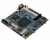
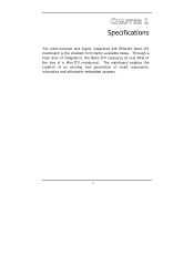
Through a high level of integration, the Nano-ITX measures at only 50% of the size of small, ergonomic, innovative and affordable embedded systems. 1 CHAPTER 1 Specifications The ultra-compact and highly integrated VIA EPIA-NX Nano-ITX mainboard is the smallest form-factor available today. The mainboard enables the creation of an exciting new generation of a Mini-ITX mainboard.
Through a high level of integration, the Nano-ITX measures at only 50% of the size of small, ergonomic, innovative and affordable embedded systems. 1 CHAPTER 1 Specifications The ultra-compact and highly integrated VIA EPIA-NX Nano-ITX mainboard is the smallest form-factor available today. The mainboard enables the creation of an exciting new generation of a Mini-ITX mainboard.

User Manual
Page 15
... out connector for Composite, S-Video, or Component (YPbPr) • 1 x Video pin connector for VGA output, CCIR656/601 video input and SMBUS • 2 x SATA connectors • 1 x Nano-ITX power connector BIOS • Award BIOS with LPC 4/8Mbit flash memory capacity Form Factor •...
... out connector for Composite, S-Video, or Component (YPbPr) • 1 x Video pin connector for VGA output, CCIR656/601 video input and SMBUS • 2 x SATA connectors • 1 x Nano-ITX power connector BIOS • Award BIOS with LPC 4/8Mbit flash memory capacity Form Factor •...
User Manual
Page 18
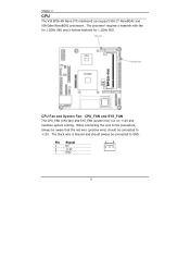
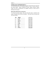
Pin Signal 1 NC 2 +12V 3 GND 13 6 The processor requires a heatsink with fan for 1.5GHz SKU and a fanless heatsink for 1.2GHz SKU. When connecting the wire to the connectors, always be aware that the red wire (positive wire) should always be connected to GND. The black wire is Ground and should be connected to +12V. CPU Fan and System Fan: CPU_FAN and SYS_FAN The CPU_FAN (CPU fan) and SYS_FAN (system fan) run on +12V and maintain system cooling. Chapter 2 CPU The VIA EPIA-NX Nano-ITX mainboard can support VIA C7 NanoBGA2 and VIA Eden NanoBGA2 processors.
Pin Signal 1 NC 2 +12V 3 GND 13 6 The processor requires a heatsink with fan for 1.5GHz SKU and a fanless heatsink for 1.2GHz SKU. When connecting the wire to the connectors, always be aware that the red wire (positive wire) should always be connected to GND. The black wire is Ground and should be connected to +12V. CPU Fan and System Fan: CPU_FAN and SYS_FAN The CPU_FAN (CPU fan) and SYS_FAN (system fan) run on +12V and maintain system cooling. Chapter 2 CPU The VIA EPIA-NX Nano-ITX mainboard can support VIA C7 NanoBGA2 and VIA Eden NanoBGA2 processors.
User Manual
Page 19
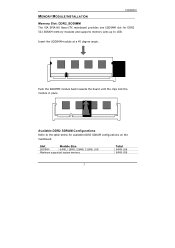
Push the SODIMM module back towards the board until the clips lock the module in place. MEMORY MODULE INSTALLATION Installation Memory Slot: DDR2_SODIMM The VIA EPIA-NX Nano-ITX mainboard provides one SODIMM slot for available DDR2 SDRAM configurations on the mainboard. Available DDR2 SDRAM Configurations Refer to the table below for DDR2 533 SDRAM memory modules and supports memory sizes up to 1GB. Slot Module Size SODIMM 64MB, 128MB, 256MB, 512MB, 1GB Maximum supported system memory Total 64MB-1GB 64MB-1GB 7 Insert the SODIMM module at a 45 degree angle.
Push the SODIMM module back towards the board until the clips lock the module in place. MEMORY MODULE INSTALLATION Installation Memory Slot: DDR2_SODIMM The VIA EPIA-NX Nano-ITX mainboard provides one SODIMM slot for available DDR2 SDRAM configurations on the mainboard. Available DDR2 SDRAM Configurations Refer to the table below for DDR2 533 SDRAM memory modules and supports memory sizes up to 1GB. Slot Module Size SODIMM 64MB, 128MB, 256MB, 512MB, 1GB Maximum supported system memory Total 64MB-1GB 64MB-1GB 7 Insert the SODIMM module at a 45 degree angle.
User Manual
Page 20
... are installed correctly to ensure that no damage will be caused. Then push down the plug firmly into the connector. Nano-ITX 12-Pin Power Connector To connect the power supply, make sure that all components are aligned. Chapter 2 CONNECTING THE POWER SUPPLY The VIA EPIA-NX Nano-ITX mainboard supports a Nano-ITX power supply for the power system.
... are installed correctly to ensure that no damage will be caused. Then push down the plug firmly into the connector. Nano-ITX 12-Pin Power Connector To connect the power supply, make sure that all components are aligned. Chapter 2 CONNECTING THE POWER SUPPLY The VIA EPIA-NX Nano-ITX mainboard supports a Nano-ITX power supply for the power system.
