User Manual
Page 6
... 5 CPU 6 CPU Fan and System Fan: CPU_FAN and SYS_FAN 6 MEMORY MODULE INSTALLATION 7 Memory Slot: DDR2_SODIMM 7 Available DDR2 SDRAM Configurations 7 CONNECTING THE POWER SUPPLY 8 Nano-ITX 12-Pin Power Connector 8 BACK PANEL PORTS 9 RJ45 LAN Port 9 CONNECTORS 10 IDE Connector: IDE 10 Case Connector: FPNL 11... Power Switch (PW_BN 11 Reset Switch (RST_SW 11 Power LED (PWR_LED 11 HDD LED (HD_LED 11 Speaker (SPEAK 11 Audio Connector: AUDIO 12 KBMS Connector: KB/MS 12 LPC...
... 5 CPU 6 CPU Fan and System Fan: CPU_FAN and SYS_FAN 6 MEMORY MODULE INSTALLATION 7 Memory Slot: DDR2_SODIMM 7 Available DDR2 SDRAM Configurations 7 CONNECTING THE POWER SUPPLY 8 Nano-ITX 12-Pin Power Connector 8 BACK PANEL PORTS 9 RJ45 LAN Port 9 CONNECTORS 10 IDE Connector: IDE 10 Case Connector: FPNL 11... Power Switch (PW_BN 11 Reset Switch (RST_SW 11 Power LED (PWR_LED 11 HDD LED (HD_LED 11 Speaker (SPEAK 11 Audio Connector: AUDIO 12 KBMS Connector: KB/MS 12 LPC...

User Manual
Page 20
Nano-ITX 12-Pin Power Connector To connect the power supply, make sure that no damage will be caused. Before inserting the power supply connector, always make sure the power plug is inserted in the proper orientation and the pins are installed correctly to ensure that all components are aligned. Then push down the plug ... 9 GND 10 +5V 11 GND 12 PWRGD 12 34 56 78 9 10 11 12 8 Downloaded from www.Manualslib.com manuals search engine Chapter 2 CONNECTING THE POWER SUPPLY The VIA EPIA-NX Nano-ITX mainboard supports a Nano-ITX power supply for the power system.
Nano-ITX 12-Pin Power Connector To connect the power supply, make sure that no damage will be caused. Before inserting the power supply connector, always make sure the power plug is inserted in the proper orientation and the pins are installed correctly to ensure that all components are aligned. Then push down the plug ... 9 GND 10 +5V 11 GND 12 PWRGD 12 34 56 78 9 10 11 12 8 Downloaded from www.Manualslib.com manuals search engine Chapter 2 CONNECTING THE POWER SUPPLY The VIA EPIA-NX Nano-ITX mainboard supports a Nano-ITX power supply for the power system.

User Manual
Page 25
... 26 GND 28 -LCLK1 30 +LCLK1 32 GND 34 -LD1C3 36 +LD1C3 38 GPIOA_CLK 40 GPIOB_DATA 1 40 Inverter Connector The mainboard provides an inverter for supplying power to support LVDS panel without any need of the LCD panel.
... 26 GND 28 -LCLK1 30 +LCLK1 32 GND 34 -LD1C3 36 +LD1C3 38 GPIOA_CLK 40 GPIOB_DATA 1 40 Inverter Connector The mainboard provides an inverter for supplying power to support LVDS panel without any need of the LCD panel.
User Manual
Page 29
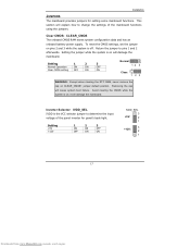
... using the jumpers. Inverter Selector: IVDD_SEL IVDD is off. Clear CMOS: CLEAR_CMOS The onboard CMOS RAM stores system configuration data and has an onboard battery power supply. Setting 1 2 3 Normal Operation ON ON OFF Clear CMOS setting OFF ON ON Normal: 12 3 Clear: 123 WARNING: Except when clearing the RTC RAM, never remove...
... using the jumpers. Inverter Selector: IVDD_SEL IVDD is off. Clear CMOS: CLEAR_CMOS The onboard CMOS RAM stores system configuration data and has an onboard battery power supply. Setting 1 2 3 Normal Operation ON ON OFF Clear CMOS setting OFF ON ON Normal: 12 3 Clear: 123 WARNING: Except when clearing the RTC RAM, never remove...

User Manual
Page 31
First unplug the power supply before adding or removing expansion cards. The "PCI & LAN" IRQ pins are typically connected to the microprocessor. CPU CX700M miniPCI Slot (bottom side) PCI Interrupt ...
First unplug the power supply before adding or removing expansion cards. The "PCI & LAN" IRQ pins are typically connected to the microprocessor. CPU CX700M miniPCI Slot (bottom side) PCI Interrupt ...

User Manual
Page 59
...Define, Min Saving, Max Saving] HDD Power Down Sets the length of time for a period of inactivity before powering down state. S3/Suspend To RAM (STR) is saved to select S1 or S3. Depends on the OS to main memory, and context is supplied only to essential components such as main ...memory and wakeup-capable devices. In this state, power is restored from www.Manualslib.com manuals search engine POWER MANAGEMENT SETUP BIOS Setup Phoenix - In this state, no system context (...
...Define, Min Saving, Max Saving] HDD Power Down Sets the length of time for a period of inactivity before powering down state. S3/Suspend To RAM (STR) is saved to select S1 or S3. Depends on the OS to main memory, and context is supplied only to essential components such as main ...memory and wakeup-capable devices. In this state, power is restored from www.Manualslib.com manuals search engine POWER MANAGEMENT SETUP BIOS Setup Phoenix - In this state, no system context (...