User Manual
Page 6
... MAINBOARD SPECIFICATIONS 2 MAINBOARD LAYOUT 4 BACK PANEL LAYOUT 4 INSTALLATION 5 CPU 6 CPU Fan and System Fan: CPU_FAN and SYS_FAN 6 MEMORY MODULE INSTALLATION 7 Memory Slot: DDR2_SODIMM 7 Available DDR2 SDRAM Configurations 7 CONNECTING THE POWER SUPPLY 8 Nano-ITX 12-Pin Power Connector 8 BACK PANEL PORTS 9 RJ45 LAN Port 9 CONNECTORS 10 IDE Connector: IDE 10 Case Connector: FPNL 11 Power Switch (PW_BN 11 Reset Switch (RST_SW 11 Power LED (PWR_LED 11 HDD LED (HD_LED 11 Speaker (SPEAK 11 Audio Connector: AUDIO 12 KBMS Connector: KB/MS 12 LPC Connector: LPC 12 LVDS Panel...
... MAINBOARD SPECIFICATIONS 2 MAINBOARD LAYOUT 4 BACK PANEL LAYOUT 4 INSTALLATION 5 CPU 6 CPU Fan and System Fan: CPU_FAN and SYS_FAN 6 MEMORY MODULE INSTALLATION 7 Memory Slot: DDR2_SODIMM 7 Available DDR2 SDRAM Configurations 7 CONNECTING THE POWER SUPPLY 8 Nano-ITX 12-Pin Power Connector 8 BACK PANEL PORTS 9 RJ45 LAN Port 9 CONNECTORS 10 IDE Connector: IDE 10 Case Connector: FPNL 11 Power Switch (PW_BN 11 Reset Switch (RST_SW 11 Power LED (PWR_LED 11 HDD LED (HD_LED 11 Speaker (SPEAK 11 Audio Connector: AUDIO 12 KBMS Connector: KB/MS 12 LPC Connector: LPC 12 LVDS Panel...

User Manual
Page 7
... 17 Panel Power Selector: PVDD_SEL 18 SLOTS 19 Mini Peripheral Component Interconnect: MINIPCI 19 PCI Interrupt Request Routing 19 BIOS SETUP 21 ENTERING SETUP 22 CONTROL KEYS 23 NAVIGATING THE BIOS MENUS 24 GETTING HELP 25 MAIN MENU 26 Standard CMOS Features 26 Advanced BIOS Features 26 Advanced Chipset Features 26 Integrated Peripherals 26 Power Management Setup 26 PnP/PCI Configurations 26 Frequency/Voltage Control 26 Load Fail-Safe Defaults 27 Load Optimized Defaults 27 Set Supervisor Password 27 Set User Password 27...
... 17 Panel Power Selector: PVDD_SEL 18 SLOTS 19 Mini Peripheral Component Interconnect: MINIPCI 19 PCI Interrupt Request Routing 19 BIOS SETUP 21 ENTERING SETUP 22 CONTROL KEYS 23 NAVIGATING THE BIOS MENUS 24 GETTING HELP 25 MAIN MENU 26 Standard CMOS Features 26 Advanced BIOS Features 26 Advanced Chipset Features 26 Integrated Peripherals 26 Power Management Setup 26 PnP/PCI Configurations 26 Frequency/Voltage Control 26 Load Fail-Safe Defaults 27 Load Optimized Defaults 27 Set Supervisor Password 27 Set User Password 27...
User Manual
Page 10
... Installed 51 Reset Configuration Data 51 Resource Controlled By 52 PCI/VGA Palette Snoop 52 Assign IRQ For VGA/USB 52 Maximum ASPM supported 52 Maximum Payload Size 52 FREQUENCY / VOLTAGE CONTROL 53 DRAM Clock 53 Auto Detect PCI Clk 53 DRAM CLOCK/DRIVE CONTROL 54 DRAM Clock 54 DRAM Timing 54 Read to Precharge (Trtp 55 Write to Read CMD (Trtp 55 Write Recovery Time (Twr 55 RDSAIT mode 55 LOAD FAIL-SAFE DEFAULTS 56 LOAD OPTIMIZED DEFAULTS 57 SET SUPERVISOR / USER PASSWORD...
... Installed 51 Reset Configuration Data 51 Resource Controlled By 52 PCI/VGA Palette Snoop 52 Assign IRQ For VGA/USB 52 Maximum ASPM supported 52 Maximum Payload Size 52 FREQUENCY / VOLTAGE CONTROL 53 DRAM Clock 53 Auto Detect PCI Clk 53 DRAM CLOCK/DRIVE CONTROL 54 DRAM Clock 54 DRAM Timing 54 Read to Precharge (Trtp 55 Write to Read CMD (Trtp 55 Write Recovery Time (Twr 55 RDSAIT mode 55 LOAD FAIL-SAFE DEFAULTS 56 LOAD OPTIMIZED DEFAULTS 57 SET SUPERVISOR / USER PASSWORD...
User Manual
Page 15
... USB 2.0 ports • 1 x LPC header • 1 x PS2 mouse/keyboard header • 2 x Fan pin connectors for CPU and System fans • 1 x LVDS panel connector • 1 x DVO connector to support 2nd LVDS panel (VT1636 add-on card required) • 1 x Audio connector: Line-out, Line-in, MIC-in, and S/PDIF out • 1 x TV out connector for Composite, S-Video, or Component (YPbPr) • 1 x Video pin connector for VGA output, CCIR656/601 video input and SMBUS • 2 x SATA connectors • 1 x Nano-ITX power connector BIOS • Award BIOS with...
... USB 2.0 ports • 1 x LPC header • 1 x PS2 mouse/keyboard header • 2 x Fan pin connectors for CPU and System fans • 1 x LVDS panel connector • 1 x DVO connector to support 2nd LVDS panel (VT1636 add-on card required) • 1 x Audio connector: Line-out, Line-in, MIC-in, and S/PDIF out • 1 x TV out connector for Composite, S-Video, or Component (YPbPr) • 1 x Video pin connector for VGA output, CCIR656/601 video input and SMBUS • 2 x SATA connectors • 1 x Nano-ITX power connector BIOS • Award BIOS with...
User Manual
Page 19
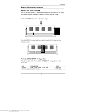
MEMORY MODULE INSTALLATION Installation Memory Slot: DDR2_SODIMM The VIA EPIA-NX Nano-ITX mainboard provides one SODIMM slot for DDR2 533 SDRAM memory modules and supports memory sizes up to the table below for available DDR2 SDRAM configurations on the mainboard. Slot Module Size SODIMM 64MB, 128MB, 256MB, 512MB, 1GB Maximum supported system memory Total 64MB-1GB 64MB-1GB 7 Downloaded from www.Manualslib.com manuals search engine Available DDR2 SDRAM Configurations Refer to 1GB. Insert...
MEMORY MODULE INSTALLATION Installation Memory Slot: DDR2_SODIMM The VIA EPIA-NX Nano-ITX mainboard provides one SODIMM slot for DDR2 533 SDRAM memory modules and supports memory sizes up to the table below for available DDR2 SDRAM configurations on the mainboard. Slot Module Size SODIMM 64MB, 128MB, 256MB, 512MB, 1GB Maximum supported system memory Total 64MB-1GB 64MB-1GB 7 Downloaded from www.Manualslib.com manuals search engine Available DDR2 SDRAM Configurations Refer to 1GB. Insert...
User Manual
Page 29
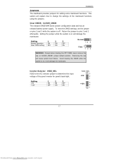
... to change the settings of the panel inverter for setting some mainboard functions. To reset the CMOS settings, set the jumper on pins 2 and 3 while the system is on CLEAR_CMOS1 jumper default position. Setting the jumper while the system is the VCC selector jumper to pins 1 and 2 afterwards. Return the jumper to determine the input voltage of the mainboard functions using the jumpers. Installation JUMPERS The mainboard provides jumpers for panel's back-light. Setting 1 2 3 Normal Operation ON ON OFF Clear CMOS setting...
... to change the settings of the panel inverter for setting some mainboard functions. To reset the CMOS settings, set the jumper on pins 2 and 3 while the system is on CLEAR_CMOS1 jumper default position. Setting the jumper while the system is the VCC selector jumper to pins 1 and 2 afterwards. Return the jumper to determine the input voltage of the mainboard functions using the jumpers. Installation JUMPERS The mainboard provides jumpers for panel's back-light. Setting 1 2 3 Normal Operation ON ON OFF Clear CMOS setting...

User Manual
Page 31
... signals to the microprocessor. SLOTS Installation Mini Peripheral Component Interconnect: MINIPCI The miniPCI slot allows you to the PCI bus INT A# ~ INT D# pins as follows: miniPCI Slot Order 1 INT B# Order 2 INT C# Order 3 INT D# Order 4 INT A# 19 Downloaded from www.Manualslib.com manuals search engine The "PCI & LAN" IRQ pins are typically connected to insert a miniPCI expansion card. First unplug the power supply before adding or removing expansion cards.
... signals to the microprocessor. SLOTS Installation Mini Peripheral Component Interconnect: MINIPCI The miniPCI slot allows you to the PCI bus INT A# ~ INT D# pins as follows: miniPCI Slot Order 1 INT B# Order 2 INT C# Order 3 INT D# Order 4 INT A# 19 Downloaded from www.Manualslib.com manuals search engine The "PCI & LAN" IRQ pins are typically connected to insert a miniPCI expansion card. First unplug the power supply before adding or removing expansion cards.

User Manual
Page 41
... 29 Downloaded from your drive must match with the drive table. Settings: [None, Auto, Manual] Settings: [CHS, LBA, Large, Auto] Formatted size of the storage device Number of cylinders Number of heads Write precompensation Cylinder location of the landing zone Number of the menu. IDE DRIVES BIOS Setup IDE HDD Auto-Detection Phoenix - AwardBIOS CMOS Setup Utility IDE Channel 0 Master [Press Enter] Item Help IDE Channel 0 Master Access Mode Capacity [Auto] [Auto] 0 MB Menu Level To auto-detect the HDD's size, head... The hard disk will not work properly...
... 29 Downloaded from your drive must match with the drive table. Settings: [None, Auto, Manual] Settings: [CHS, LBA, Large, Auto] Formatted size of the storage device Number of cylinders Number of heads Write precompensation Cylinder location of the landing zone Number of the menu. IDE DRIVES BIOS Setup IDE HDD Auto-Detection Phoenix - AwardBIOS CMOS Setup Utility IDE Channel 0 Master [Press Enter] Item Help IDE Channel 0 Master Access Mode Capacity [Auto] [Auto] 0 MB Menu Level To auto-detect the HDD's size, head... The hard disk will not work properly...

User Manual
Page 43
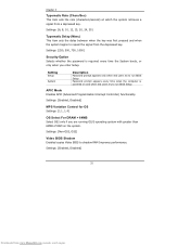
..." functions. BIOS Setup First/Second/Third Boot Device Set the boot device sequence as BIOS attempts to behave as 10-key Forces keypad to load the disk operating system. Setting LS120 Hard Disk CD-ROM ZIP100 USB-FDD USB-ZIP USB-CDROM Legacy LAN Disabled Description Boot from LS-120 drive Boot from the HDD Boot from CD-ROM Boot from ATAPI ZIP drive Boot from USB floppy drive Boot from USB ZIP drive Boot from USB CDROM Boot from network drive Disable the boot device sequence Boot Other Device Enables the system to boot from alternate devices if...
..." functions. BIOS Setup First/Second/Third Boot Device Set the boot device sequence as BIOS attempts to behave as 10-key Forces keypad to load the disk operating system. Setting LS120 Hard Disk CD-ROM ZIP100 USB-FDD USB-ZIP USB-CDROM Legacy LAN Disabled Description Boot from LS-120 drive Boot from the HDD Boot from CD-ROM Boot from ATAPI ZIP drive Boot from USB floppy drive Boot from USB ZIP drive Boot from USB CDROM Boot from network drive Disable the boot device sequence Boot Other Device Enables the system to boot from alternate devices if...
User Manual
Page 44
... 64MB of RAM on the system. Setting Setup System Description Password prompt appears only when end users try to run BIOS Setup APIC Mode Enables APIC (Advanced Programmable Interrupt Controller) functionality. Settings: [Non-OS2, OS2] Video BIOS Shadow Enabled copies Video BIOS to repeat the signal from the depressed key. Settings: [Enabled, Disabled] 32 Downloaded from a depressed key. Settings: [Enabled, Disabled] MPS Variation Control for OS Settings: [1.1, 1.4] OS Select For DRAM > 64MB Select OS2 only if you enter Setup. Chapter...
... 64MB of RAM on the system. Setting Setup System Description Password prompt appears only when end users try to run BIOS Setup APIC Mode Enables APIC (Advanced Programmable Interrupt Controller) functionality. Settings: [Non-OS2, OS2] Video BIOS Shadow Enabled copies Video BIOS to repeat the signal from the depressed key. Settings: [Enabled, Disabled] 32 Downloaded from a depressed key. Settings: [Enabled, Disabled] MPS Variation Control for OS Settings: [1.1, 1.4] OS Select For DRAM > 64MB Select OS2 only if you enter Setup. Chapter...

User Manual
Page 52
... This item is used to auto or manual. Settings: [Enabled, Disabled] AGP Master 1 WS Write Settings:[Enabled, Disabled] AGP Master 1 WS Read Settings:[Enabled, Disabled] AGP 3.0 Calibration Cycle Settings: [Enabled, Disabled] VGA Share Memory Size Settings: [Disabled, 32M, 64M, 128M] Direct Frame Buffer Settings: [Enabled, Disabled] 40 Downloaded from www.Manualslib.com manuals search engine Chapter 3 AGP Driving Control This item is used to signal driving current on AGP cards to enable or disable the caching of display data for the video memory of the processor.
... This item is used to auto or manual. Settings: [Enabled, Disabled] AGP Master 1 WS Write Settings:[Enabled, Disabled] AGP Master 1 WS Read Settings:[Enabled, Disabled] AGP 3.0 Calibration Cycle Settings: [Enabled, Disabled] VGA Share Memory Size Settings: [Disabled, 32M, 64M, 128M] Direct Frame Buffer Settings: [Enabled, Disabled] 40 Downloaded from www.Manualslib.com manuals search engine Chapter 3 AGP Driving Control This item is used to signal driving current on AGP cards to enable or disable the caching of display data for the video memory of the processor.

User Manual
Page 56
AwardBIOS CMOS Setup Utility VIA OnChip PCI Device [Auto] [Disabled] Item Help Menu Level : Move Enter: Select F5: Previous Values +/-/PU/PD: Value F10: Save F6: Fail-Safe Defaults ESC: Exit F1: General Help F7: Optimized Defaults Azalia HAD Controller Settings:[Auto, Disabled] OnBoard LAN Boot ROM Settings:[Enabled, Disabled] 44 Downloaded from www.Manualslib.com manuals search engine Chapter 3 VIA ONCHIP PCI DEVICE Azalia HDA Controller OnBoard LAN Boot ROM Phoenix -
AwardBIOS CMOS Setup Utility VIA OnChip PCI Device [Auto] [Disabled] Item Help Menu Level : Move Enter: Select F5: Previous Values +/-/PU/PD: Value F10: Save F6: Fail-Safe Defaults ESC: Exit F1: General Help F7: Optimized Defaults Azalia HAD Controller Settings:[Auto, Disabled] OnBoard LAN Boot ROM Settings:[Enabled, Disabled] 44 Downloaded from www.Manualslib.com manuals search engine Chapter 3 VIA ONCHIP PCI DEVICE Azalia HDA Controller OnBoard LAN Boot ROM Phoenix -

User Manual
Page 57
... engine AwardBIOS CMOS Setup Utility USB Device Setting [Enabled] [Enabled] [High Speed] [Enabled] [Enabled] *** USB Mass Storage Device Boot Setting *** UFDDA USB Floppy UFDDB USB Floppy No Device [Auto mode] No Device [Auto mode] No Device [Auto mode] No Device [Auto mode] No Device [Auto mode] No Device [Auto mode] No Device [Auto mode] No Device [Auto mode] Item Help Menu Level [Enable] or [Disable] Universal Host Controller Interface for Universal Serial Bus : Move Enter: Select F5: Previous Values +/-/PU/PD: Value F10: Save F6: Fail-Safe Defaults ESC: Exit...
... engine AwardBIOS CMOS Setup Utility USB Device Setting [Enabled] [Enabled] [High Speed] [Enabled] [Enabled] *** USB Mass Storage Device Boot Setting *** UFDDA USB Floppy UFDDB USB Floppy No Device [Auto mode] No Device [Auto mode] No Device [Auto mode] No Device [Auto mode] No Device [Auto mode] No Device [Auto mode] No Device [Auto mode] No Device [Auto mode] Item Help Menu Level [Enable] or [Disable] Universal Host Controller Interface for Universal Serial Bus : Move Enter: Select F5: Previous Values +/-/PU/PD: Value F10: Save F6: Fail-Safe Defaults ESC: Exit...

User Manual
Page 58
The USB MSD always boot up as hard disc. 46 Downloaded from www.Manualslib.com manuals search engine The USB MSD always boot up type. Chapter 3 USB Keyboard Function Enable or disable Legacy support of USB Keyboard Settings: [Enabled, Disabled] USB Storage Function Enable or disable Legacy support of USB Mass Storage Settings: [Enabled, Disabled] No Device Setting Auto mode FDD mode HDD mode Description According to contents of USB MSD decide boot up as flooppy disk.
The USB MSD always boot up as hard disc. 46 Downloaded from www.Manualslib.com manuals search engine The USB MSD always boot up type. Chapter 3 USB Keyboard Function Enable or disable Legacy support of USB Keyboard Settings: [Enabled, Disabled] USB Storage Function Enable or disable Legacy support of USB Mass Storage Settings: [Enabled, Disabled] No Device Setting Auto mode FDD mode HDD mode Description According to contents of USB MSD decide boot up as flooppy disk.
User Manual
Page 63
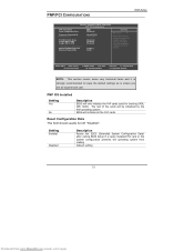
... PnP operating system BIOS will only initialize the PnP cards used for booting (VGA, IDE, SCSI). AwardBIOS CMOS Setup Utility PnP / PCI Configurations PNP OS Installed Reset Configuration Data Resources Controlled By x IRQ Resources PCI/VGA Palette Snoop Assign IRQ For VGA Assign IRQ For USB ** PCI Express relative items ** Maximum ASPM supported Maximum Payload Size [No] [Disabled] [Auto(ESCD)] Press Enter [Disabled] [Enabled] [Enabled] [L0s&L1] [4096] Item Help Menu Level Select Yes if you are using a Plug and Play capable...
... PnP operating system BIOS will only initialize the PnP cards used for booting (VGA, IDE, SCSI). AwardBIOS CMOS Setup Utility PnP / PCI Configurations PNP OS Installed Reset Configuration Data Resources Controlled By x IRQ Resources PCI/VGA Palette Snoop Assign IRQ For VGA Assign IRQ For USB ** PCI Express relative items ** Maximum ASPM supported Maximum Payload Size [No] [Disabled] [Auto(ESCD)] Press Enter [Disabled] [Enabled] [Enabled] [L0s&L1] [4096] Item Help Menu Level Select Yes if you are using a Plug and Play capable...

User Manual
Page 64
... Downloaded from www.Manualslib.com manuals search engine Setting Auto(ESCD) Manual Description BIOS will automatically assign IRQ, DMA and memory base address fields Unlocks "IRQ Resources" for manual configuration PCI/VGA Palette Snoop Settings: [Disabled, Enabled] Assign IRQ For VGA/USB Assign IRQ for the PCI Express devices. Chapter 3 Resource Controlled By Enables the BIOS to automatically configure all the Plug-and-Play compatible devices. The unit is byte. Settings: [Disabled, Enabled] Maximum ASPM supported Control maximum level of ASPM supported...
... Downloaded from www.Manualslib.com manuals search engine Setting Auto(ESCD) Manual Description BIOS will automatically assign IRQ, DMA and memory base address fields Unlocks "IRQ Resources" for manual configuration PCI/VGA Palette Snoop Settings: [Disabled, Enabled] Assign IRQ For VGA/USB Assign IRQ for the PCI Express devices. Chapter 3 Resource Controlled By Enables the BIOS to automatically configure all the Plug-and-Play compatible devices. The unit is byte. Settings: [Disabled, Enabled] Maximum ASPM supported Control maximum level of ASPM supported...

User Manual
Page 65
... the pulses so that the spikes of the pulses create EMI (Electromagnetic Interference). AwardBIOS CMOS Setup Utility Frequency / Voltage Control DRAM Clock/Drive Control Auto Detect PCI Clk Spread Spectrum [Press Enter] [Enabled] [0.25%] Item Help Menu Level : Move Enter: Select F5: Previous Values +/-/PU/PD: Value F10: Save F6: Fail-Safe Defaults ESC: Exit F1: General Help F7: Optimized Defaults DRAM Clock The chipset supports synchronous and asynchronous mode between host clock and DRAM clock frequency. FREQUENCY / VOLTAGE CONTROL BIOS Setup Phoenix -
... the pulses so that the spikes of the pulses create EMI (Electromagnetic Interference). AwardBIOS CMOS Setup Utility Frequency / Voltage Control DRAM Clock/Drive Control Auto Detect PCI Clk Spread Spectrum [Press Enter] [Enabled] [0.25%] Item Help Menu Level : Move Enter: Select F5: Previous Values +/-/PU/PD: Value F10: Save F6: Fail-Safe Defaults ESC: Exit F1: General Help F7: Optimized Defaults DRAM Clock The chipset supports synchronous and asynchronous mode between host clock and DRAM clock frequency. FREQUENCY / VOLTAGE CONTROL BIOS Setup Phoenix -

User Manual
Page 66
...] [Auto By SPD] 2.5 / 4 Disabled 4T 07T 4T 25T 3T [2T] [1T/2T] [4T] [Auto] 03 Item Help Menu Level : Move Enter: Select F5: Previous Values +/-/PU/PD: Value F10: Save F6: Fail-Safe Defaults ESC: Exit F1: General Help F7: Optimized Defaults DRAM Clock The chipset supports synchronous and asynchronous mode between host clock and DRAM clock frequency. Changing the value from www.Manualslib.com manuals search engine Chapter 3 DRAM CLOCK/DRIVE CONTROL...
...] [Auto By SPD] 2.5 / 4 Disabled 4T 07T 4T 25T 3T [2T] [1T/2T] [4T] [Auto] 03 Item Help Menu Level : Move Enter: Select F5: Previous Values +/-/PU/PD: Value F10: Save F6: Fail-Safe Defaults ESC: Exit F1: General Help F7: Optimized Defaults DRAM Clock The chipset supports synchronous and asynchronous mode between host clock and DRAM clock frequency. Changing the value from www.Manualslib.com manuals search engine Chapter 3 DRAM CLOCK/DRIVE CONTROL...

User Manual
Page 77
The driver utilities and software menu screen should run automatically, click on the screen. NOTE: D: might not be the drive letter of the CD-ROM/DVD-ROM in your system. 65 Downloaded from www.Manualslib.com manuals search engine If the CD does not run automatically after closing the CD-ROM or DVD-ROM drive. Then type: "D:\Setup.exe". Driver Installation Running the Driver Utilities CD To start using the CD, insert the CD into the CD-ROM or DVD-ROM drive. The CD should then appear on the "Start" button and select "Run..."
The driver utilities and software menu screen should run automatically, click on the screen. NOTE: D: might not be the drive letter of the CD-ROM/DVD-ROM in your system. 65 Downloaded from www.Manualslib.com manuals search engine If the CD does not run automatically after closing the CD-ROM or DVD-ROM drive. Then type: "D:\Setup.exe". Driver Installation Running the Driver Utilities CD To start using the CD, insert the CD into the CD-ROM or DVD-ROM drive. The CD should then appear on the "Start" button and select "Run..."
User Manual
Page 78
... onboard VIA audio chip. VIA GigaLAN Driver: Enhances the onboard optional VIA VT6122 10/100/1000M LAN chip. VIA USB 2.0 Driver: Enhances VIA USB 2.0 ports. VIA Graphics Driver: Enhances the onboard VIA graphic chip. VIA RAID Driver: Support for SATA RAID devices. 66 Downloaded from www.Manualslib.com manuals search engine Chapter 4 CD CONTENT VIA 4in1 Drivers: Contains VIA ATAPI Vendor Support Driver (enables the performance enhancing bus mastering functions on ATA-capable Hard Disk Drives and ensures IDE device compatibility), AGP VxD Driver (provides service routines to your VGA...
... onboard VIA audio chip. VIA GigaLAN Driver: Enhances the onboard optional VIA VT6122 10/100/1000M LAN chip. VIA USB 2.0 Driver: Enhances VIA USB 2.0 ports. VIA Graphics Driver: Enhances the onboard VIA graphic chip. VIA RAID Driver: Support for SATA RAID devices. 66 Downloaded from www.Manualslib.com manuals search engine Chapter 4 CD CONTENT VIA 4in1 Drivers: Contains VIA ATAPI Vendor Support Driver (enables the performance enhancing bus mastering functions on ATA-capable Hard Disk Drives and ensures IDE device compatibility), AGP VxD Driver (provides service routines to your VGA...
