
User Manual
Page 5
...USB Cable Connection 23 LED and Reset Cable Connection 24 CCChhhaaapppttteeerrr444 BIOS Setup...26 Entering the BIOS Setup Menu 27 Control Keys ...28 Navigating the BIOS Menus 29 Getting Help...30 Main Menu...31 Standard CMOS Features 31 Advanced BIOS Features 31 Advanced Chipset Features 31 Integrated Peripherals 31 Power ...33 Time...33 Video...33 Halt On ...33 SATA Drives ...34 SATA Channel 0 ...34 SATA Channel 1 ...34 Compact Flash Disk 35 Advanced BIOS Features 37 Virus Warning...37 CPU L1 & L2 Cache 37 CPU L2 Cache ECC Checking 37 Quick Power On Self-Test 38 First/Second/Third...
...USB Cable Connection 23 LED and Reset Cable Connection 24 CCChhhaaapppttteeerrr444 BIOS Setup...26 Entering the BIOS Setup Menu 27 Control Keys ...28 Navigating the BIOS Menus 29 Getting Help...30 Main Menu...31 Standard CMOS Features 31 Advanced BIOS Features 31 Advanced Chipset Features 31 Integrated Peripherals 31 Power ...33 Time...33 Video...33 Halt On ...33 SATA Drives ...34 SATA Channel 0 ...34 SATA Channel 1 ...34 Compact Flash Disk 35 Advanced BIOS Features 37 Virus Warning...37 CPU L1 & L2 Cache 37 CPU L2 Cache ECC Checking 37 Quick Power On Self-Test 38 First/Second/Third...

User Manual
Page 6
... 40 CPU Features...41 Delay Prior to Thermal 41 Thermal Management 41 Hard Disk Boot Priority 42 Advanced Chipset Features 43 Memory Hole...43 System BIOS Cacheable 43 Video RAM Cacheable 43 AGP Fast Write ...43 Internal VGA Control 44 AGP 3.0 Calibration Cycle 44 VGA Share Memory Size 44 Direct... Frame Buffer 44 CPU & PCI Bus Control 45 PCI Master 0 WS Write 45 PCI Delay Transaction 45 VIA PWR Management 45 Integrated Peripherals 46 OnChip IDE Channel 1 46 IDE HDD Block Mode 46 SATA Controller ...46 Azalia HDA Controller 46 Onboard LAN Boot...
... 40 CPU Features...41 Delay Prior to Thermal 41 Thermal Management 41 Hard Disk Boot Priority 42 Advanced Chipset Features 43 Memory Hole...43 System BIOS Cacheable 43 Video RAM Cacheable 43 AGP Fast Write ...43 Internal VGA Control 44 AGP 3.0 Calibration Cycle 44 VGA Share Memory Size 44 Direct... Frame Buffer 44 CPU & PCI Bus Control 45 PCI Master 0 WS Write 45 PCI Delay Transaction 45 VIA PWR Management 45 Integrated Peripherals 46 OnChip IDE Channel 1 46 IDE HDD Block Mode 46 SATA Controller ...46 Azalia HDA Controller 46 Onboard LAN Boot...

User Manual
Page 11
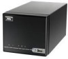
N701 User's Manual Back Panel I/O Ports • 1 x RJ45 LAN port • 2 x USB 2.0 ports • 1 x Audio jack for Line-Out and Mic/Line-In BIOS • Award BIOS with SPI 4/8Mbit flash memory capacity Supported Operating Systems • Microsoft Windows 2000 • Microsoft Windows XP • Microsoft Windows CE • Microsoft Windows XPe &#...
N701 User's Manual Back Panel I/O Ports • 1 x RJ45 LAN port • 2 x USB 2.0 ports • 1 x Audio jack for Line-Out and Mic/Line-In BIOS • Award BIOS with SPI 4/8Mbit flash memory capacity Supported Operating Systems • Microsoft Windows 2000 • Microsoft Windows XP • Microsoft Windows CE • Microsoft Windows XPe &#...

User Manual
Page 23
Please short pin 3 & 5, pin 4 & 6, pin 7 & 9 and pin 8 & 10. SPI (Serial Peripheral Interface): JSPI This pin header is not in use. Pin Signal Pin Signal 1 SPI_VCC 2 GND 3 SPI_SS0 4 SPI_CLK 5 SPI_DI 6 SPI_DO 7 Key 8 RST_SW 8 2 1 15 N701 User's Manual KB/MS Connector The mainboard provides a PS2 pin header to attach a PS2 keyboard and mouse. 2 10 Pin Signal 1 VCCE 3 NC 5 GND 7 KB_DT 9 KB_CK Pin Signal 2 VCCE 4 Key 6 GND 8 MS_DT 10 MS_CK 1 9 Note: When the pin header is used to connect with SPI BIOS programming fixture.
Please short pin 3 & 5, pin 4 & 6, pin 7 & 9 and pin 8 & 10. SPI (Serial Peripheral Interface): JSPI This pin header is not in use. Pin Signal Pin Signal 1 SPI_VCC 2 GND 3 SPI_SS0 4 SPI_CLK 5 SPI_DI 6 SPI_DO 7 Key 8 RST_SW 8 2 1 15 N701 User's Manual KB/MS Connector The mainboard provides a PS2 pin header to attach a PS2 keyboard and mouse. 2 10 Pin Signal 1 VCCE 3 NC 5 GND 7 KB_DT 9 KB_CK Pin Signal 2 VCCE 4 Key 6 GND 8 MS_DT 10 MS_CK 1 9 Note: When the pin header is used to connect with SPI BIOS programming fixture.

User Manual
Page 34
N701 User's Manual CHHAAPPTTEERR 4 BIOS SETUP This chapter gives a detailed explanation of the BIOS setup functions. 26
N701 User's Manual CHHAAPPTTEERR 4 BIOS SETUP This chapter gives a detailed explanation of the BIOS setup functions. 26

User Manual
Page 35
N701 User's Manual Entering the BIOS Setup Menu Power on the computer and press during the beginning of the boot sequence to enter the BIOS setup menu. If you missed the BIOS setup entry point, restart the system and try again. 27
N701 User's Manual Entering the BIOS Setup Menu Power on the computer and press during the beginning of the boot sequence to enter the BIOS setup menu. If you missed the BIOS setup entry point, restart the system and try again. 27

User Manual
Page 37
Use the / and / arrow keys to display the sub-menu. Descriptions of the selected/highlighted category are displayed at the bottom of the screen. To exit the sub-menu, press . 29 Press to select any item or sub-menu. N701 User's Manual Navigating the BIOS Menus The main menu displays all the BIOS setup categories. An arrow symbol next to a field indicates that a sub-menu is available (see figure below).
Use the / and / arrow keys to display the sub-menu. Descriptions of the selected/highlighted category are displayed at the bottom of the screen. To exit the sub-menu, press . 29 Press to select any item or sub-menu. N701 User's Manual Navigating the BIOS Menus The main menu displays all the BIOS setup categories. An arrow symbol next to a field indicates that a sub-menu is available (see figure below).

User Manual
Page 38
You can display this screen from any menu/sub-menu by pressing . The help screen. 30 Press to exit the help screen displays the keys for using and navigating the BIOS setup. N701 User's Manual Getting Help The BIOS setup program provides a "General Help" screen.
You can display this screen from any menu/sub-menu by pressing . The help screen. 30 Press to exit the help screen displays the keys for using and navigating the BIOS setup. N701 User's Manual Getting Help The BIOS setup program provides a "General Help" screen.

User Manual
Page 39
... Main Menu The Main Menu contains twelve setup functions and two exit choices. Advanced Chipset Features Use this menu to set basic system configurations. Advanced BIOS Features Use this menu to set the advanced features available on your system. Use arrow keys to select the items and press to set onboard...
... Main Menu The Main Menu contains twelve setup functions and two exit choices. Advanced Chipset Features Use this menu to set basic system configurations. Advanced BIOS Features Use this menu to set the advanced features available on your system. Use arrow keys to select the items and press to set onboard...

User Manual
Page 40
N701 User's Manual PC Health Status This menu shows the PC health status. Load Optimized Defaults Use this menu option to set the BIOS supervisor password. Set Supervisor Password Use this menu option to set the system frequency and voltage control. Set User Password Use this menu to load BIOS default settings for optimal and high performance system operations. Frequency/Voltage Control Use this menu option to set the BIOS user password. Exit Without Saving Discard all BIOS setting changes and exit setup. 32 Save & Exit Setup Save BIOS setting changes and exit setup.
N701 User's Manual PC Health Status This menu shows the PC health status. Load Optimized Defaults Use this menu option to set the BIOS supervisor password. Set Supervisor Password Use this menu option to set the system frequency and voltage control. Set User Password Use this menu to load BIOS default settings for optimal and high performance system operations. Frequency/Voltage Control Use this menu option to set the BIOS user password. Exit Without Saving Discard all BIOS setting changes and exit setup. 32 Save & Exit Setup Save BIOS setting changes and exit setup.

User Manual
Page 45
... boot sector virus protection Turns off CPU L1 & L2 cache Turns on the screen and alarm beep. N701 User's Manual Advanced BIOS Features Virus Warning Allows you to write data into this area, BIOS will show a warning message on CPU L1 & L2 cache CPU L2 Cache ECC Checking Settings: [Enabled, Disabled] 37
... boot sector virus protection Turns off CPU L1 & L2 cache Turns on the screen and alarm beep. N701 User's Manual Advanced BIOS Features Virus Warning Allows you to write data into this area, BIOS will show a warning message on CPU L1 & L2 cache CPU L2 Cache ECC Checking Settings: [Enabled, Disabled] 37

User Manual
Page 46
Settings Off On Description Forces keypad to behave as arrow keys Forces keypad to boot from alternate devices if the system fails to behave as BIOS attempts to enable shorter boot up time First/Second/Third Boot Device Set the boot device sequence as 10-key Typematic Rate Setting Enables "Typematic ...
Settings Off On Description Forces keypad to behave as arrow keys Forces keypad to boot from alternate devices if the system fails to behave as BIOS attempts to enable shorter boot up time First/Second/Third Boot Device Set the boot device sequence as 10-key Typematic Rate Setting Enables "Typematic ...

User Manual
Page 47
... the system retrieves a signal from the depressed key. Settings Description Setup Password prompt appears only when end users try to run BIOS Setup System Password prompt appears every time when the computer is required every time the System boots, or only when you are ...64MB of RAM on the system. Settings: [Disabled, Enabled] 39 Settings: [Non-OS2, OS2] HDD S.M.A.R.T Capability Settings: [Disabled, Enabled] Video BIOS Shadow Enabled copies Video BIOS to repeat the signal from a depressed key. Settings: [6, 8, 10, 12, 15, 20, 24, 30] Typematic Delay (Msec) This item...
... the system retrieves a signal from the depressed key. Settings Description Setup Password prompt appears only when end users try to run BIOS Setup System Password prompt appears every time when the computer is required every time the System boots, or only when you are ...64MB of RAM on the system. Settings: [Disabled, Enabled] 39 Settings: [Non-OS2, OS2] HDD S.M.A.R.T Capability Settings: [Disabled, Enabled] Video BIOS Shadow Enabled copies Video BIOS to repeat the signal from a depressed key. Settings: [6, 8, 10, 12, 15, 20, 24, 30] Typematic Delay (Msec) This item...

User Manual
Page 51
Do not change these settings unless you are familiar with the chipset. Memory Hole Settings: [Disabled, 15M - 16M] System BIOS Cacheable Settings: [Disabled, Enabled] Video RAM Cacheable Settings: [Disabled, Enabled] AGP Fast Write Settings: [Disabled, Enabled] 43 N701 User's Manual Advanced Chipset Features Caution: The Advanced Chipset Features menu is used for optimizing the chipset functions.
Do not change these settings unless you are familiar with the chipset. Memory Hole Settings: [Disabled, 15M - 16M] System BIOS Cacheable Settings: [Disabled, Enabled] Video RAM Cacheable Settings: [Disabled, Enabled] AGP Fast Write Settings: [Disabled, Enabled] 43 N701 User's Manual Advanced Chipset Features Caution: The Advanced Chipset Features menu is used for optimizing the chipset functions.
User Manual
Page 60
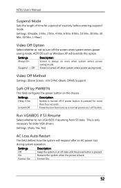
...: [Disable, 1 Min, 2 Min, 4 Min, 6 Min, 8 Min, 10 Min, 20 Min, 30 Min, 40 Min, 1 Hour] Video Off Option Select whether or not to run VGA BIOS if resuming from S3 state. Settings: [Auto, Yes, No] AC Loss Auto Restart The field defines how the system will override this option.
...: [Disable, 1 Min, 2 Min, 4 Min, 6 Min, 8 Min, 10 Min, 20 Min, 30 Min, 40 Min, 1 Hour] Video Off Option Select whether or not to run VGA BIOS if resuming from S3 state. Settings: [Auto, Yes, No] AC Loss Auto Restart The field defines how the system will override this option.
User Manual
Page 64
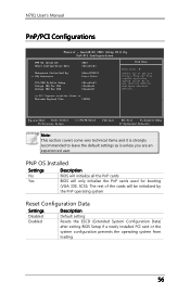
... be initialized by the PnP operating system Reset Configuration Data Settings Disabled Enabled Description Default setting Resets the ESCD (Extended System Configuration Data) after exiting BIOS Setup if a newly installed PCI card or the system configuration prevents the operating system from loading 56 N701 User's Manual PnP/PCI Configurations Note: This...
... be initialized by the PnP operating system Reset Configuration Data Settings Disabled Enabled Description Default setting Resets the ESCD (Extended System Configuration Data) after exiting BIOS Setup if a newly installed PCI card or the system configuration prevents the operating system from loading 56 N701 User's Manual PnP/PCI Configurations Note: This...

User Manual
Page 65
...Plug-and-Play compatible devices. The unit is byte. Settings: [128, 256, 512, 1024, 2048, 4096] 57 Settings Auto(ESCD) Manual Description BIOS will automatically assign IRQ, DMA and memory base address fields Unlocks "IRQ Resources" for USB devices. Settings: [Disabled, Enabled] Assign IRQ for USB Assign...configuration PCI/VGA Palette Snoop Some non-standard VGA display cards may not show colors properly. N701 User's Manual Resources Controlled By Enable the BIOS to set whether MPEG ISA/VESA VGA Cards can work with PCI/VGA or not. When enabled, a PCI/VGA can work with ...
...Plug-and-Play compatible devices. The unit is byte. Settings: [128, 256, 512, 1024, 2048, 4096] 57 Settings Auto(ESCD) Manual Description BIOS will automatically assign IRQ, DMA and memory base address fields Unlocks "IRQ Resources" for USB devices. Settings: [Disabled, Enabled] Assign IRQ for USB Assign...configuration PCI/VGA Palette Snoop Some non-standard VGA display cards may not show colors properly. N701 User's Manual Resources Controlled By Enable the BIOS to set whether MPEG ISA/VESA VGA Cards can work with PCI/VGA or not. When enabled, a PCI/VGA can work with ...

User Manual
Page 69
The default optimized values are set by the mainboard manufacturer to load the default optimized BIOS values. Entering "Y" and press to provide a stable system with optimized performance. N701 User's Manual Load Optimized Defaults This option is for restoring all the default optimized BIOS settings. Entering "N" will cancel the load optimized defaults request. 61
The default optimized values are set by the mainboard manufacturer to load the default optimized BIOS values. Entering "Y" and press to provide a stable system with optimized performance. N701 User's Manual Load Optimized Defaults This option is for restoring all the default optimized BIOS settings. Entering "N" will cancel the load optimized defaults request. 61

User Manual
Page 70
N701 User's Manual Set Supervisor/User Password Supervisor Password User Password This option is run. When a password has been set, a password prompt will be displayed whenever BIOS Setup is for setting a password for entering BIOS Setup. This prevents an unauthorized person from changing any part of your system configuration. 62
N701 User's Manual Set Supervisor/User Password Supervisor Password User Password This option is run. When a password has been set, a password prompt will be displayed whenever BIOS Setup is for setting a password for entering BIOS Setup. This prevents an unauthorized person from changing any part of your system configuration. 62

User Manual
Page 71
... password typed now will need to be reentered to be changed . The new password will clear any previously set to eight characters in the "Advanced BIOS Features" section for more details. 63 A message will show up to request the password each time the system is enabled, the... . To cancel the process press . To set . To cancel the process press . This would prevent unauthorized use of passwords you can be accessed but the BIOS settings cannot be set password from CMOS memory. To disable the password, press when prompted to confirm disabling the password.
... password typed now will need to be reentered to be changed . The new password will clear any previously set to eight characters in the "Advanced BIOS Features" section for more details. 63 A message will show up to request the password each time the system is enabled, the... . To cancel the process press . To set . To cancel the process press . This would prevent unauthorized use of passwords you can be accessed but the BIOS settings cannot be set password from CMOS memory. To disable the password, press when prompted to confirm disabling the password.