English Owners Manual
Page 5
... call 23 Receiving a DSC call 24 Test Calls 25 Position Request and Reply 27 Putting the radio into standby 28 Disabling automatic channel switching.... 28 Installing the Hardware 29 Mounting the radio 29 Connecting the radio 30 Connecting to a GPS receiver 31 Connecting to a Chartplotter 33 Connecting to an External Speaker...
... call 23 Receiving a DSC call 24 Test Calls 25 Position Request and Reply 27 Putting the radio into standby 28 Disabling automatic channel switching.... 28 Installing the Hardware 29 Mounting the radio 29 Connecting the radio 30 Connecting to a GPS receiver 31 Connecting to a Chartplotter 33 Connecting to an External Speaker...

English Owners Manual
Page 33
...screws to the mounting surface. Mark the edges of the mounting surface. special requirements of the bracket on the mounting surface. 3. Install the radio back into the mounting bracket. 2. The radio displays the last 10 distress calls and the last 20 nondistress calls ... heat sink on page 24). Deactivating automatic switching and then forgetting it can easily accommodate the best location. Hex nut Spring washer 5. Installing the Hardware Mounting the radio Your radio can : xx Properly support the weight of the radio, approximately 2.2 pounds or 1.0 kilograms. ...
...screws to the mounting surface. Mark the edges of the mounting surface. special requirements of the bracket on the mounting surface. 3. Install the radio back into the mounting bracket. 2. The radio displays the last 10 distress calls and the last 20 nondistress calls ... heat sink on page 24). Deactivating automatic switching and then forgetting it can easily accommodate the best location. Hex nut Spring washer 5. Installing the Hardware Mounting the radio Your radio can : xx Properly support the weight of the radio, approximately 2.2 pounds or 1.0 kilograms. ...

English Owners Manual
Page 34
... of your power source. 2. Connect the PL-259 connector from the antenna lead-in wires to 15.8 VDC). 50 Ω impedance Power leads should be installed a minimum of 3 feet from 35 to the POSITIVE (+) side of your radio. antennas over 3 dB should be kept as short as Minimum 4 foot, 3 dB rated... #14 AWG copper wire for Minimum RG-58 lead-in connector, male PL-259 30 English UM380_20101221.indd 30 4/13/2011 11:25:17 AM Install your power source. 3. See Antenna Selection and Installation on the back of your antenna according to 3 dB be...
... of your power source. 2. Connect the PL-259 connector from the antenna lead-in wires to 15.8 VDC). 50 Ω impedance Power leads should be installed a minimum of 3 feet from 35 to the POSITIVE (+) side of your radio. antennas over 3 dB should be kept as short as Minimum 4 foot, 3 dB rated... #14 AWG copper wire for Minimum RG-58 lead-in connector, male PL-259 30 English UM380_20101221.indd 30 4/13/2011 11:25:17 AM Install your power source. 3. See Antenna Selection and Installation on the back of your antenna according to 3 dB be...
English Owners Manual
Page 39
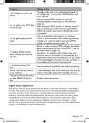
... more information. Things to Try Reset the radio back to the weather channel when this happens. Check to make sure the FIPS codes in some installations it may catch a hazard alert in your GPS receiver supports the NMEA parameters described in NMEA Operation on . Sometimes the Weather Alert Watch may be... User MMSI. Make sure that your radio were entered correctly (see any hazard alerts. In severe cases of noise interference, it may be necessary to install a noise suppression kit.
... more information. Things to Try Reset the radio back to the weather channel when this happens. Check to make sure the FIPS codes in some installations it may catch a hazard alert in your GPS receiver supports the NMEA parameters described in NMEA Operation on . Sometimes the Weather Alert Watch may be... User MMSI. Make sure that your radio were entered correctly (see any hazard alerts. In severe cases of noise interference, it may be necessary to install a noise suppression kit.
English Owners Manual
Page 51
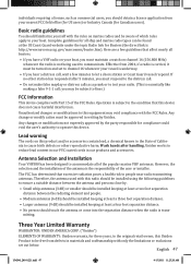
... This device complies with Part 15 of the FCC Rules. If no other reproductive harm. Uniden works to test your vessel is not being used with this radio should be installed using the following guidelines to operate this product and/or accessories contain lead, a chemical known... could void the user's authority to ensure a suitable distance between the radiating element and people. • Medium antennas (6 dB) should be installed keeping at least a three foot separation distance. • Larger antennas (9 dB) should touch the antenna or come into the separation distance when...
... This device complies with Part 15 of the FCC Rules. If no other reproductive harm. Uniden works to test your vessel is not being used with this radio should be installed using the following guidelines to operate this product and/or accessories contain lead, a chemical known... could void the user's authority to ensure a suitable distance between the radiating element and people. • Medium antennas (6 dB) should be installed keeping at least a three foot separation distance. • Larger antennas (9 dB) should touch the antenna or come into the separation distance when...

English Owners Manual
Page 52
...either, at its original packaging). Warrantor, at its representatives in this Operating Guide you to this warranty at any system not manufactured by Uniden, or (F) installed or programmed by anyone other than as detailed by the Operating Guide for a defect or malfunction covered by this warranty, (E) used in ... in connection with equipment or parts or as part of any conversion kits, subassemblies, or any configurations not sold by Uniden, (C) improperly installed, (D) serviced or repaired by warrantor or its option, repair or replace the defective unit and return it .
...either, at its original packaging). Warrantor, at its representatives in this Operating Guide you to this warranty at any system not manufactured by Uniden, or (F) installed or programmed by anyone other than as detailed by the Operating Guide for a defect or malfunction covered by this warranty, (E) used in ... in connection with equipment or parts or as part of any conversion kits, subassemblies, or any configurations not sold by Uniden, (C) improperly installed, (D) serviced or repaired by warrantor or its option, repair or replace the defective unit and return it .

