Owners Manual
Page 1
CMX660 PROFESSIONAL MOBILE CB RADIO Owner's Manual © 2017 Uniden America Corporation Irving, Texas U01UT418ZZZ(0) Printed in Vietnam
CMX660 PROFESSIONAL MOBILE CB RADIO Owner's Manual © 2017 Uniden America Corporation Irving, Texas U01UT418ZZZ(0) Printed in Vietnam

Owners Manual
Page 3
... POWER 10 Ground Information 11 Connect Power 11 MARINE INSTALLATION 12 CONNECT ANTENNA 12 Safety Notice 13 INSTALL MICROPHONE HANGER/ CONNECT MICROPHONE 14 Install Microphone Hanger 14 Connect Microphone 14 Disconnect the Microphone 15 INSTALL RADIO BRACKET/INSTALL RADIO 15 Attach Side Rails 15 Attach Bracket/Install Radio 16 EMERGENCY OPERATION 17 USING YOUR CMX660 17 LCD DISPLAY 17 BASIC OPERATIONS 19 Turn On/Off 19 Transmit/Receive 20 Adjust Volume 20 Select Channel before Transmit...
... POWER 10 Ground Information 11 Connect Power 11 MARINE INSTALLATION 12 CONNECT ANTENNA 12 Safety Notice 13 INSTALL MICROPHONE HANGER/ CONNECT MICROPHONE 14 Install Microphone Hanger 14 Connect Microphone 14 Disconnect the Microphone 15 INSTALL RADIO BRACKET/INSTALL RADIO 15 Attach Side Rails 15 Attach Bracket/Install Radio 16 EMERGENCY OPERATION 17 USING YOUR CMX660 17 LCD DISPLAY 17 BASIC OPERATIONS 19 Turn On/Off 19 Transmit/Receive 20 Adjust Volume 20 Select Channel before Transmit...

Owners Manual
Page 4
Adjust Squelch 21 Automatic Noise Limiter (ANL/HI-CUT 21 Adjust Radio Sensitivity (LO/DX 22 CHANNEL SCAN 23 WEATHER MODE (WX MODE 23 Set Weather Scan 24 Set Weather Alert Mode 25 MENU OPERATION 25 Set Dimmer 25 Set Key Beep 26 Set Roger Beep 27 Set Battery Check 27 Set FLIP 28 PREVENTIVE MAINTENANCE 28 MAINTENANCE 28 TROUBLESHOOTING 29 SERVICING YOUR RADIO 30 SPECIFICATIONS 31 FCC PART 15 & IC COMPLIANCE 34 FCC PART 15 COMPLIANCE 34 IC COMPLIANCE 34 ONE-YEAR LIMITED WARRANTY 35 RADIO CODE DEFINITIONS 39
Adjust Squelch 21 Automatic Noise Limiter (ANL/HI-CUT 21 Adjust Radio Sensitivity (LO/DX 22 CHANNEL SCAN 23 WEATHER MODE (WX MODE 23 Set Weather Scan 24 Set Weather Alert Mode 25 MENU OPERATION 25 Set Dimmer 25 Set Key Beep 26 Set Roger Beep 27 Set Battery Check 27 Set FLIP 28 PREVENTIVE MAINTENANCE 28 MAINTENANCE 28 TROUBLESHOOTING 29 SERVICING YOUR RADIO 30 SPECIFICATIONS 31 FCC PART 15 & IC COMPLIANCE 34 FCC PART 15 COMPLIANCE 34 IC COMPLIANCE 34 ONE-YEAR LIMITED WARRANTY 35 RADIO CODE DEFINITIONS 39

Owners Manual
Page 5
... CMX660 is under the seat to provide years of the Federal Communications Commission (FCC). Its slim profile can fit easily under the jurisdiction of trouble-free service. Please read this Owner's Manual carefully to ensure you gain the optimum performance of the 40 AM frequencies authorized by the Federal Communications Commission (FCC). The Citizens Band Radio Service is...
... CMX660 is under the seat to provide years of the Federal Communications Commission (FCC). Its slim profile can fit easily under the jurisdiction of trouble-free service. Please read this Owner's Manual carefully to ensure you gain the optimum performance of the 40 AM frequencies authorized by the Federal Communications Commission (FCC). The Citizens Band Radio Service is...

Owners Manual
Page 7
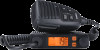
WHAT'S IN THE BOX CMX660 Radio Microphone Microphone Hanger with Hardware CMX660 Slide Mount Bracket with Hardware CMX660 DC Power Cord with Fuse Not Shown: Printed Materials 7
WHAT'S IN THE BOX CMX660 Radio Microphone Microphone Hanger with Hardware CMX660 Slide Mount Bracket with Hardware CMX660 DC Power Cord with Fuse Not Shown: Printed Materials 7

Owners Manual
Page 10
... and adjust wiring that is turned off. As an alternative, the power cord may interfere with the driver or passenger. Select a location that may be careful not to the Ignition Switch Accessory Terminal. The basic steps to install this unit are: • Connect Power • Connect Antenna • Install Microphone Hanger/Connect Microphone • Install Radio Bracket/Install Radio CONNECT POWER Uniden recommends connecting the power lead to create a short circuit...
... and adjust wiring that is turned off. As an alternative, the power cord may interfere with the driver or passenger. Select a location that may be careful not to the Ignition Switch Accessory Terminal. The basic steps to install this unit are: • Connect Power • Connect Antenna • Install Microphone Hanger/Connect Microphone • Install Radio Bracket/Install Radio CONNECT POWER Uniden recommends connecting the power lead to create a short circuit...

Owners Manual
Page 11
..., or negative (-) battery terminal. 11 Connect the power cord to the vehicle motor block. Next, connect the black power cord to the positive (+) battery terminal or other convenient point. Connect Power 1. The CMX660 can operate on 12VDC power supply. Connect the red DC power cord from the radio. 2. Ground Information This radio may be installed and used in any 12volt DC negative ground...
..., or negative (-) battery terminal. 11 Connect the power cord to the vehicle motor block. Next, connect the black power cord to the positive (+) battery terminal or other convenient point. Connect Power 1. The CMX660 can operate on 12VDC power supply. Connect the red DC power cord from the radio. 2. Ground Information This radio may be installed and used in any 12volt DC negative ground...

Owners Manual
Page 12
... the maximum power output of your radio with no antenna or with a damaged antenna cable. This can damage the radio. 12 Only a properly matched antenna system will allow maximum power transfer from the 50-ohm transmission line to prevent electrolysis between the fittings in the hull and the water. Turn the vehicle off . It is limited by installing an inferior...
... the maximum power output of your radio with no antenna or with a damaged antenna cable. This can damage the radio. 12 Only a properly matched antenna system will allow maximum power transfer from the 50-ohm transmission line to prevent electrolysis between the fittings in the hull and the water. Turn the vehicle off . It is limited by installing an inferior...

Owners Manual
Page 13
... efficiency is less than that Uniden does not specify or supply any antenna with this radio must provide a separation distance of a full quarter-wave whip antenna. Once your antenna is installed, tune it using the radio. An SWR higher than 2:1 before using a Standing-Wave Ratio (SWR) meter (not included): set it to channel 20 and adjust the antenna until the SWR is less than 2:1 can damage...
... efficiency is less than that Uniden does not specify or supply any antenna with this radio must provide a separation distance of a full quarter-wave whip antenna. Once your antenna is installed, tune it using the radio. An SWR higher than 2:1 before using a Standing-Wave Ratio (SWR) meter (not included): set it to channel 20 and adjust the antenna until the SWR is less than 2:1 can damage...

Owners Manual
Page 14
Insert the MIC jack into the radio's MIC socket until it back along the cord. 2. Connect Microphone Mic Jack 1. Find a location to be sure the connection is locked. 14 Hang the microphone onto the hanger. Adjust wiring if necessary. 2. Pull back the MIC jack rubber cover and slide it clicks into place. 3. Gently tug on the cable to install the microphone hanger. INSTALL MICROPHONE HANGER/CONNECT MICROPHONE Install Microphone Hanger 1. When you install the hanger, take the same precautions as installing the radio (see page 10).
Insert the MIC jack into the radio's MIC socket until it back along the cord. 2. Connect Microphone Mic Jack 1. Find a location to be sure the connection is locked. 14 Hang the microphone onto the hanger. Adjust wiring if necessary. 2. Pull back the MIC jack rubber cover and slide it clicks into place. 3. Gently tug on the cable to install the microphone hanger. INSTALL MICROPHONE HANGER/CONNECT MICROPHONE Install Microphone Hanger 1. When you install the hanger, take the same precautions as installing the radio (see page 10).

Owners Manual
Page 15
... Microphone 1. Attach Side Rails 1. Slide the rubber cover down the MIC jack's lock tab; tug gently on top of the radio and insert L-tabs into the L-tab slots. If you want to use the extension cable, connect the cable to the radio and the MIC to seal it back along the sides of a surface. INSTALL RADIO BRACKET/INSTALL RADIO The CMX660...
... Microphone 1. Attach Side Rails 1. Slide the rubber cover down the MIC jack's lock tab; tug gently on top of the radio and insert L-tabs into the L-tab slots. If you want to use the extension cable, connect the cable to the radio and the MIC to seal it back along the sides of a surface. INSTALL RADIO BRACKET/INSTALL RADIO The CMX660...

Owners Manual
Page 16
... damage any wiring or hardware. L-Tab (2 on each rail) L-Tab Slot (2 on each side) Slide Mount Latch (1 on the radio. Using the screws provided, screw the bracket into place. If mounting the radio in a vehicle, for example, screw the bracket onto the top of the way or relocate the radio bracket. 2. Use the screws provided to fasten the guide rails...
... damage any wiring or hardware. L-Tab (2 on each rail) L-Tab Slot (2 on each side) Slide Mount Latch (1 on the radio. Using the screws provided, screw the bracket into place. If mounting the radio in a vehicle, for example, screw the bracket onto the top of the way or relocate the radio bracket. 2. Use the screws provided to fasten the guide rails...

Owners Manual
Page 28
Set FLIP Use FLIP to give you are no user- 28 Press again to cancel. Press LO/DX to exit menus or press any key to flip the LCD. 3. Be sure all electrical connections are tight. A double beep sounds. Check the SWR. 2. Inspect antenna coaxial cable for wear or breaks in shielding. 4. There are mounting... the radio upside down if you years of trouble-free service. MAINTENANCE The CMX660 is designed to turn the LCD upside-down . 1. Press LO/DX...
Set FLIP Use FLIP to give you are no user- 28 Press again to cancel. Press LO/DX to exit menus or press any key to flip the LCD. 3. Be sure all electrical connections are tight. A double beep sounds. Check the SWR. 2. Inspect antenna coaxial cable for wear or breaks in shielding. 4. There are mounting... the radio upside down if you years of trouble-free service. MAINTENANCE The CMX660 is designed to turn the LCD upside-down . 1. Press LO/DX...

Owners Manual
Page 29
serviceable parts inside. Except for your warranty. Twist to do so may void your CMX660. TROUBLESHOOTING In the event of the fuse holder together. Use only the fuse specified for the fuse in the DC power cord, no maintenance is required. Check fuse. Check antenna. To replace a blown fuse: 1. Check volume and squelch. Press ends of system malfunction, perform the following procedures: PROBLEM Unit does...
serviceable parts inside. Except for your warranty. Twist to do so may void your CMX660. TROUBLESHOOTING In the event of the fuse holder together. Use only the fuse specified for the fuse in the DC power cord, no maintenance is required. Check fuse. Check antenna. To replace a blown fuse: 1. Check volume and squelch. Press ends of system malfunction, perform the following procedures: PROBLEM Unit does...

Owners Manual
Page 30
... the user's responsibility to specify the correct model number and serial number of the unit. 30 Check your alternator. SERVICING YOUR RADIO It is not set to CB mode. Make sure your power wires have a good connection. When ordering parts, be fully charged. Battery power check displays Lo or HI. If you consult a qualified radio/ telephone technician for troubleshooting and FAQ information.
... the user's responsibility to specify the correct model number and serial number of the unit. 30 Check your alternator. SERVICING YOUR RADIO It is not set to CB mode. Make sure your power wires have a good connection. When ordering parts, be fully charged. Battery power check displays Lo or HI. If you consult a qualified radio/ telephone technician for troubleshooting and FAQ information.

Owners Manual
Page 31
SPECIFICATIONS GENERAL Channel: Frequency Range: Frequency Control: Antenna Impedance: Power Input: Current Drain TX: RX: Operating Temperature: Accessories: 40 26.965 ~ 27.405 MHz PLL Synthesizer 50 ohms, unbalanced 13.8VDC AM Full Modulation: 1.5A (max) At no signal: 400mA (max) -22°F to 140°F -30°C to 60°C DC Power Cord with Built-In Fuse Microphone Microphone Hanger with Screws Mounting Bracket with Screws Owner's Manual Part 95 Subpart D (FCC Rules) 31
SPECIFICATIONS GENERAL Channel: Frequency Range: Frequency Control: Antenna Impedance: Power Input: Current Drain TX: RX: Operating Temperature: Accessories: 40 26.965 ~ 27.405 MHz PLL Synthesizer 50 ohms, unbalanced 13.8VDC AM Full Modulation: 1.5A (max) At no signal: 400mA (max) -22°F to 140°F -30°C to 60°C DC Power Cord with Built-In Fuse Microphone Microphone Hanger with Screws Mounting Bracket with Screws Owner's Manual Part 95 Subpart D (FCC Rules) 31

Owners Manual
Page 32
Size (W x D x H): Weight: Antenna Connector TRANSMITTER Output Power: Hum and Noise: Frequency Tolerance: Spurious Rejection: RECEIVER Sensitivity at 10 dB S/N Maximum Sensitivity Squelch Sensitivity Signal Meter S-9: 4 in . D (without knobs and jacks) (102 mm W x 24.6 mm H x 98.2 mm D) 0.9 Pounds M-Type UNIT Watts dB % NOMINAL 4 40 ±0.002 dBc UNIT dBm -70 NOMINAL -110 dBm -114 dBm Step 1: -107 (MIN) dBm Step 7: -47 (MAX) dBm -67 32 W x 0.97 in . H x 3.86 in.
Size (W x D x H): Weight: Antenna Connector TRANSMITTER Output Power: Hum and Noise: Frequency Tolerance: Spurious Rejection: RECEIVER Sensitivity at 10 dB S/N Maximum Sensitivity Squelch Sensitivity Signal Meter S-9: 4 in . D (without knobs and jacks) (102 mm W x 24.6 mm H x 98.2 mm D) 0.9 Pounds M-Type UNIT Watts dB % NOMINAL 4 40 ±0.002 dBc UNIT dBm -70 NOMINAL -110 dBm -114 dBm Step 1: -107 (MIN) dBm Step 7: -47 (MAX) dBm -67 32 W x 0.97 in . H x 3.86 in.

Owners Manual
Page 35
... ou modification non approuvé expressément par la partie responsable pourrait annuler le droit à l'utilisateur de faire fonctionner cet équipement. ONE-YEAR LIMITED WARRANTY Important: Evidence of the device. WARRANTOR: UNIDEN AMERICA CORPORATION ("Uniden") ELEMENTS OF WARRANTY: Uniden warrants,... accepter les interférences, incluant celles pouvant nuire à son fonctionnement normal. subject to the original retail owner, this device must accept any interference, including interference that may cause undesired operation of original purchase is required for...
... ou modification non approuvé expressément par la partie responsable pourrait annuler le droit à l'utilisateur de faire fonctionner cet équipement. ONE-YEAR LIMITED WARRANTY Important: Evidence of the device. WARRANTOR: UNIDEN AMERICA CORPORATION ("Uniden") ELEMENTS OF WARRANTY: Uniden warrants,... accepter les interférences, incluant celles pouvant nuire à son fonctionnement normal. subject to the original retail owner, this device must accept any interference, including interference that may cause undesired operation of original purchase is required for...

Owners Manual
Page 36
... as detailed by this warranty, (E) used in any configurations not sold by Uniden, (C) improperly installed, (D) serviced or repaired by someone other than an authorized Uniden service center for a defect or malfunction covered by the owner's manual for this product. STATEMENT OF REMEDY: In the event that the product does...of this warranty. Uniden Product to this warranty at its option, repair or replace the defective unit and return it to the original user shall terminate and be free from defects in materials and craftsmanship with only the limitations or exclusions set out below.
... as detailed by this warranty, (E) used in any configurations not sold by Uniden, (C) improperly installed, (D) serviced or repaired by someone other than an authorized Uniden service center for a defect or malfunction covered by the owner's manual for this product. STATEMENT OF REMEDY: In the event that the product does...of this warranty. Uniden Product to this warranty at its option, repair or replace the defective unit and return it to the original user shall terminate and be free from defects in materials and craftsmanship with only the limitations or exclusions set out below.

Owners Manual
Page 39
... Stop transmitting OK, message received Relay message Busy, stand by Out of service, leaving air In service, subject to channel Traffic accident at Traffic tie up at I have a message for faster communication and better understanding. RADIO CODE DEFINITIONS The following list contains common "10-Codes" used by CODE MEANING 10-34 Trouble at this station 10-35 Confidential information 10...
... Stop transmitting OK, message received Relay message Busy, stand by Out of service, leaving air In service, subject to channel Traffic accident at Traffic tie up at I have a message for faster communication and better understanding. RADIO CODE DEFINITIONS The following list contains common "10-Codes" used by CODE MEANING 10-34 Trouble at this station 10-35 Confidential information 10...


