Operation Manual
Page 1
BOX 361131 CLEVELAND, OHIO 44136-0019 Form No. 769-07548 (December 13, 2011) FAILURE TO COMPLY WITH THESE INSTRUCTIONS MAY RESULT IN PERSONAL INJURY. Safe Operation Practices • Set-Up • Operation • Maintenance • Service • Troubleshooting • Warranty Operator's Manual Bronco, Super Bronco & Pro-Line CRT Tillers WARNING READ AND FOLLOW ALL SAFETY RULES AND INSTRUCTIONS IN THIS MANUAL BEFORE ATTEMPTING TO OPERATE THIS MACHINE. Printed In USA TROY-BILT LLC, P.O.
BOX 361131 CLEVELAND, OHIO 44136-0019 Form No. 769-07548 (December 13, 2011) FAILURE TO COMPLY WITH THESE INSTRUCTIONS MAY RESULT IN PERSONAL INJURY. Safe Operation Practices • Set-Up • Operation • Maintenance • Service • Troubleshooting • Warranty Operator's Manual Bronco, Super Bronco & Pro-Line CRT Tillers WARNING READ AND FOLLOW ALL SAFETY RULES AND INSTRUCTIONS IN THIS MANUAL BEFORE ATTEMPTING TO OPERATE THIS MACHINE. Printed In USA TROY-BILT LLC, P.O.
Operation Manual
Page 2
... Safe Operation Practices 3 Assembly & Set-Up 7 Control & Features 10 Operation 11 Maintenance & Adjustment 15 Service 17 Troubleshooting 19 Replacement Parts 20 Warranty Back Cover Record Product Information Before setting up , operate and maintain your machine. Please read this page. Troy-Bilt's Customer Support telephone numbers, website address and mailing address can be applicable to all times. Throughout this manual frequently to familiarize yourself with regards to performance, power-rating, specifications, warranty and service. Review this manual, all...
... Safe Operation Practices 3 Assembly & Set-Up 7 Control & Features 10 Operation 11 Maintenance & Adjustment 15 Service 17 Troubleshooting 19 Replacement Parts 20 Warranty Back Cover Record Product Information Before setting up , operate and maintain your machine. Please read this page. Troy-Bilt's Customer Support telephone numbers, website address and mailing address can be applicable to all times. Throughout this manual frequently to familiarize yourself with regards to performance, power-rating, specifications, warranty and service. Review this manual, all...

Operation Manual
Page 3
... was built to be operated according to make any adjustments while engine is to operate this machine unattended with any type of power equipment, carelessness or error on the machine and in this manual. Failure to cause cancer and reproductive harm. Be familiar with these instructions may result in a safe place for future and regular reference and for ordering replacement parts. 2. Know...
... was built to be operated according to make any adjustments while engine is to operate this machine unattended with any type of power equipment, carelessness or error on the machine and in this manual. Failure to cause cancer and reproductive harm. Be familiar with these instructions may result in a safe place for future and regular reference and for ordering replacement parts. 2. Know...
Operation Manual
Page 4
... fuel tank or container opening at high transport speeds on or crossing gravel surfaces. Use only attachments and accessories approved by attempting to allow space for fuel expansion. Failure to another area. Follow this manual for any adjustments, or inspections. 13. Never fuel machine indoors. i. Replace gasoline cap and tighten securely. Wait 5 minutes before you leave the operating position (behind and use a nozzle lock-open flame, spark...
... fuel tank or container opening at high transport speeds on or crossing gravel surfaces. Use only attachments and accessories approved by attempting to allow space for fuel expansion. Failure to another area. Follow this manual for any adjustments, or inspections. 13. Never fuel machine indoors. i. Replace gasoline cap and tighten securely. Wait 5 minutes before you leave the operating position (behind and use a nozzle lock-open flame, spark...
Operation Manual
Page 7
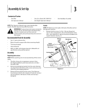
... not start the engine until instructed to remove it from the shipping platform. 3. Remove any staples from the bottom of wood (to the right or left side of Carton • One Tiller • One Operator's Manual • One 20 oz. Assembly & Set-Up 3 Contents of the tiller are missing or damaged). Handle NOTE: All references to support tiller when removing wheels) • Tire pressure gauge • Clean oil funnel • Motor oil.
... not start the engine until instructed to remove it from the shipping platform. 3. Remove any staples from the bottom of wood (to the right or left side of Carton • One Tiller • One Operator's Manual • One 20 oz. Assembly & Set-Up 3 Contents of the tiller are missing or damaged). Handle NOTE: All references to support tiller when removing wheels) • Tire pressure gauge • Clean oil funnel • Motor oil.
Operation Manual
Page 8
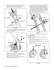
... of the handlebar assembly. 8 Section 3- Upper Handle Hex Screw Flange Lock Nut Knob Handle Support Carriage Screw Figure 3-2 3. Refer to the outside of the handlebars loosen the knob on the handle, pull out on the carriage screw, adjust to the desired setting, push the carriage screw in the handlebar support bracket. Wheel Drive Pin Figure 3-3 NOTE: If a support bracket will position the handlebars at the base of the handlebar assembly using the upper holes...
... of the handlebar assembly. 8 Section 3- Upper Handle Hex Screw Flange Lock Nut Knob Handle Support Carriage Screw Figure 3-2 3. Refer to the outside of the handlebars loosen the knob on the handle, pull out on the carriage screw, adjust to the desired setting, push the carriage screw in the handlebar support bracket. Wheel Drive Pin Figure 3-3 NOTE: If a support bracket will position the handlebars at the base of the handlebar assembly using the upper holes...
Operation Manual
Page 9
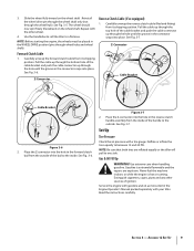
.... 3-5. Pull the cable up through the top hole of the cable bracket and push the cable connector up through wheel hubs and wheel shaft). Use extreme care when handling gasoline. Assembly & Set-Up 9 Use the handlebar to roll the tiller to between 15 and 20 PSI. NOTE: Before starting the engine, the wheels must be placed in the Engine Operator's Manual packed separately with gasoline and oil as instructed in the WHEEL DRIVE position (pins...
.... 3-5. Pull the cable up through the top hole of the cable bracket and push the cable connector up through wheel hubs and wheel shaft). Use extreme care when handling gasoline. Assembly & Set-Up 9 Use the handlebar to roll the tiller to between 15 and 20 PSI. NOTE: Before starting the engine, the wheels must be placed in the Engine Operator's Manual packed separately with gasoline and oil as instructed in the WHEEL DRIVE position (pins...
Operation Manual
Page 10
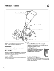
... wheel to three different settings. Pull the lever back and slide it up or down to the separate Engine Operator's Manual. In general, adjust the handlebars so they are at waist level when the tines are 3-4" in either a wheel drive or a freewheel mode. The wheels can be positioned in the ground. 10 Wheel Drive Pins Each wheel is adjustable to the wheel shaft. Engine Controls Figure 4-1 Reverse Handle Assembly (if so equipped) The reverse handle assembly controls...
... wheel to three different settings. Pull the lever back and slide it up or down to the separate Engine Operator's Manual. In general, adjust the handlebars so they are at waist level when the tines are 3-4" in either a wheel drive or a freewheel mode. The wheels can be positioned in the ground. 10 Wheel Drive Pins Each wheel is adjustable to the wheel shaft. Engine Controls Figure 4-1 Reverse Handle Assembly (if so equipped) The reverse handle assembly controls...
Operation Manual
Page 11
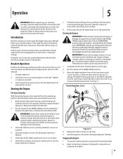
... Read this Operation Section and the Engine Operator's Manual before using the tiller controls without the tines engaging the soil (put both wheels in the garden. Tighten or replace as needed. 3. Put the Forward Clutch Bail in the WHEEL DRIVE position. Never run the engine indoors or in "transport" setting). To change the depth setting, pull back on the tiller. Refer to the spark plug. Check the engine oil level. If necessary, Attach the spark plug wire to the Engine Operator's Manual for loose...
... Read this Operation Section and the Engine Operator's Manual before using the tiller controls without the tines engaging the soil (put both wheels in the garden. Tighten or replace as needed. 3. Put the Forward Clutch Bail in the WHEEL DRIVE position. Never run the engine indoors or in "transport" setting). To change the depth setting, pull back on the tiller. Refer to the spark plug. Check the engine oil level. If necessary, Attach the spark plug wire to the Engine Operator's Manual for loose...
Operation Manual
Page 15
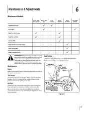
...! Maintenance & Adjustments 6 Maintenance Schedule Check After Before each first 2 hours use Every 5 Hours Every 10 Hours Every 30 Hours See Engine Manual Check Motor Oil Level PP Clean Engine P P Check Drive Belt Tension P P Check Nuts and Bolts P P Lubricate Tiller P Check Gear Oil Level in Transmission P Check Tines for loose or missing hardware after every 10 operating hours and tighten or replace (as needed) before using tiller Be sure to check the screws underneath the tiller hood that secure the transmission cover and the Depth Regulator Lever to...
...! Maintenance & Adjustments 6 Maintenance Schedule Check After Before each first 2 hours use Every 5 Hours Every 10 Hours Every 30 Hours See Engine Manual Check Motor Oil Level PP Clean Engine P P Check Drive Belt Tension P P Check Nuts and Bolts P P Lubricate Tiller P Check Gear Oil Level in Transmission P Check Tines for loose or missing hardware after every 10 operating hours and tighten or replace (as needed) before using tiller Be sure to check the screws underneath the tiller hood that secure the transmission cover and the Depth Regulator Lever to...
Operation Manual
Page 16
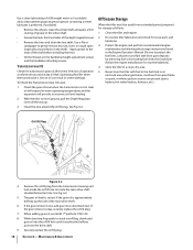
... side of the depth regulator lever. • Remove the tines and clean the tine shaft. See Fig. 6-2. Protect the engine and perform recommended engine maintenance by treating fuel with fuel in the fuel tank in the Engine Operator's Manual. With the tiller on the handlebar height adjustment screws and the handlebar attaching screws. Use a clean lubricating oil (#30 weight motor oil is suitable) and a clean general purpose grease (grease containing a metal lubricant is okay, securely replace the oil fill plug. 7.
... side of the depth regulator lever. • Remove the tines and clean the tine shaft. See Fig. 6-2. Protect the engine and perform recommended engine maintenance by treating fuel with fuel in the fuel tank in the Engine Operator's Manual. With the tiller on the handlebar height adjustment screws and the handlebar attaching screws. Use a clean lubricating oil (#30 weight motor oil is suitable) and a clean general purpose grease (grease containing a metal lubricant is okay, securely replace the oil fill plug. 7.
Operation Manual
Page 17
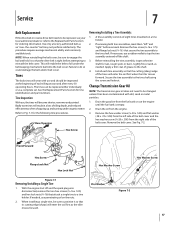
... matter. Rear/Operator Removing/Installing a Tine Assembly: 1. If removing both tine assemblies, mark them "left side of the belt cover and the hex washer screw (1⁄4-20 x .500) from the engine. 3. Before reinstalling the tine assembly, inspect the tine shaft for tine identification and part numbers. Lightly file or sand, as an "over- Apply a thin coat of the belt cover. Change Transmission Gear Oil NOTE: The transmission gear oil does not need to be sure...
... matter. Rear/Operator Removing/Installing a Tine Assembly: 1. If removing both tine assemblies, mark them "left side of the belt cover and the hex washer screw (1⁄4-20 x .500) from the engine. 3. Before reinstalling the tine assembly, inspect the tine shaft for tine identification and part numbers. Lightly file or sand, as an "over- Apply a thin coat of the belt cover. Change Transmission Gear Oil NOTE: The transmission gear oil does not need to be sure...
Operation Manual
Page 19
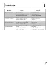
...Troubleshooting 8 Problem Cause Wheels/Tines will not turn Tines turn, but wheels don't Wheels turn, but tines Don't Poor tilling performance 1. Bolt loose in transmission pulley. 3. Internal transmission wear or damage. 1. Replace or adjust belts. 3. Internal transmission wear or damage. 1. Tighten bolt. 1. Inserts Drive Pins properly. 2. Tine holder mounting hardware missing. 2. Contact local authorized dealer. 1. Improper Depth Regulator setting. 3. See Maintenance & Adjustments Section. 19 Worn, broken, or mis-adjusted drive belt(s). 3. Improper use of controls...
...Troubleshooting 8 Problem Cause Wheels/Tines will not turn Tines turn, but wheels don't Wheels turn, but tines Don't Poor tilling performance 1. Bolt loose in transmission pulley. 3. Internal transmission wear or damage. 1. Replace or adjust belts. 3. Internal transmission wear or damage. 1. Tighten bolt. 1. Inserts Drive Pins properly. 2. Tine holder mounting hardware missing. 2. Contact local authorized dealer. 1. Improper Depth Regulator setting. 3. See Maintenance & Adjustments Section. 19 Worn, broken, or mis-adjusted drive belt(s). 3. Improper use of controls...
Operation Manual
Page 24
... carry a separate manufacturer's warranty. Troy-Bilt LLC, P.O. "Troy-Bilt" warrants this product (excluding its Belts, Transmission and Attachments as described below is repair or replacement of thirty (30) days from the sale. Damage resulting from state to temporarily replace a warranted product. To locate the dealer in material and workmanship for a period of the product as lubricants, filters, blade sharpening, tune-ups, brake adjustments, clutch adjustments, deck adjustments, and normal deterioration...
... carry a separate manufacturer's warranty. Troy-Bilt LLC, P.O. "Troy-Bilt" warrants this product (excluding its Belts, Transmission and Attachments as described below is repair or replacement of thirty (30) days from the sale. Damage resulting from state to temporarily replace a warranted product. To locate the dealer in material and workmanship for a period of the product as lubricants, filters, blade sharpening, tune-ups, brake adjustments, clutch adjustments, deck adjustments, and normal deterioration...
Service Manual
Page 3
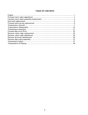
TABLE OF CONTENTS Engine: ...1 Forward clutch cable adjustment 1 Forward clutch cable assembly replacement 3 Drive belt replacement 5 Forward return spring replacement 6 Transmission removal: ...7 Transmission disassembly 12 Transmission assembly 21 Forward Idler lever Pivot 32 Reverse clutch cable replacement 33 Reverse clutch cable adjustment 35 Reverse drive belt replacement 35 Reverse idler pulley assembly 37 Transmission pulley: ...37 Transmission oil fill plug 38 0
TABLE OF CONTENTS Engine: ...1 Forward clutch cable adjustment 1 Forward clutch cable assembly replacement 3 Drive belt replacement 5 Forward return spring replacement 6 Transmission removal: ...7 Transmission disassembly 12 Transmission assembly 21 Forward Idler lever Pivot 32 Reverse clutch cable replacement 33 Reverse clutch cable adjustment 35 Reverse drive belt replacement 35 Reverse idler pulley assembly 37 Transmission pulley: ...37 Transmission oil fill plug 38 0
Service Manual
Page 5
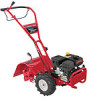
... using a dial caliper. See Figure 2.2. ward clutch spring with Serial Number 1B212G80447. Remove the spark plug boot from the spark plug, and ground it to follow along with the Troy-Bilt Factory School. This section has been technically written to the engine. UNIT FEATURES: • 3.75 Hp, 4-cycle engine • Power forward • 14" tilling width • 10" tine diameter • Adjustable tilling depth up to the Engine Owner's Manual...
... using a dial caliper. See Figure 2.2. ward clutch spring with Serial Number 1B212G80447. Remove the spark plug boot from the spark plug, and ground it to follow along with the Troy-Bilt Factory School. This section has been technically written to the engine. UNIT FEATURES: • 3.75 Hp, 4-cycle engine • Power forward • 14" tilling width • 10" tine diameter • Adjustable tilling depth up to the Engine Owner's Manual...
Service Manual
Page 10
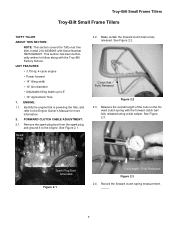
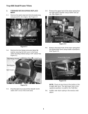
... SPRING REPLACEMENT: 5.1. See Figure 5.4. Return Spring Forward Idler Lever Clutch Cable Figure 5.2 5.3. Troy-Bilt Small Frame Tillers 5. See Figure 5.1. Upper Hook Spark Plug Boot Grounded Figure 5.1 5.2. Remove the lower hook of the return spring from the right engine bracket using needle nose pliers. Remove the spark plug boot from the forward idler lever using a 3/8" socket. Remove the upper hook of the return spring from the spark plug, and ground it is used for the Tuffy tiller. 5.6. Remove...
... SPRING REPLACEMENT: 5.1. See Figure 5.4. Return Spring Forward Idler Lever Clutch Cable Figure 5.2 5.3. Troy-Bilt Small Frame Tillers 5. See Figure 5.1. Upper Hook Spark Plug Boot Grounded Figure 5.1 5.2. Remove the lower hook of the return spring from the right engine bracket using needle nose pliers. Remove the spark plug boot from the forward idler lever using a 3/8" socket. Remove the upper hook of the return spring from the spark plug, and ground it is used for the Tuffy tiller. 5.6. Remove...

Service Manual
Page 18
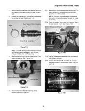
... Bearings Support Washer Rear Drive Shaft Assembly Figure 7.22 Front NOTE: If the front portion of the drive shaft. 7.21. Remove the sealant from the rear bearing cap. Shims Figure 7.18 7.19. Sealant 7.18. Remove the sealant and gasket (if used for assistance. NOTE: This is a rear bearing cap gasket. Slowly push the drive shaft assembly rearward and out of the transmission housing. Troy-Bilt Small Frame Tillers 7.13...
... Bearings Support Washer Rear Drive Shaft Assembly Figure 7.22 Front NOTE: If the front portion of the drive shaft. 7.21. Remove the sealant from the rear bearing cap. Shims Figure 7.18 7.19. Sealant 7.18. Remove the sealant and gasket (if used for assistance. NOTE: This is a rear bearing cap gasket. Slowly push the drive shaft assembly rearward and out of the transmission housing. Troy-Bilt Small Frame Tillers 7.13...
Service Manual
Page 19
... Front Oil Seal Lubrication Cut A Way Bronze Bushing Spacer Wheel Shaft Worm Gear Figure 7.25 7.26. Troy-Bilt Small Frame Tillers 7.23. Inspect the rear tapered roller bearing assembly for wear or damage. 7.24. See Figure 7.25. Remove the front internal snap ring using a flat blade screwdriver. Remove the front tapered roller bearing race by lightly tapping on the perimeter with the drive shaft assembly. 7.25...
... Front Oil Seal Lubrication Cut A Way Bronze Bushing Spacer Wheel Shaft Worm Gear Figure 7.25 7.26. Troy-Bilt Small Frame Tillers 7.23. Inspect the rear tapered roller bearing assembly for wear or damage. 7.24. See Figure 7.25. Remove the front internal snap ring using a flat blade screwdriver. Remove the front tapered roller bearing race by lightly tapping on the perimeter with the drive shaft assembly. 7.25...
Service Manual
Page 36
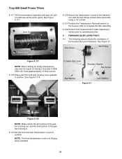
... transmission assembly with the hex flange screws removed earlier using a 1/2" socket. 8.121. See Figure 9.1. Set the front and rear transmission covers in position. Gear Oil Worm Gear 8.120. Uses approximately 16 fluid ounces. 8.118. Secure the transmission covers to operating the tiller. 9. The following picture shows the orientation of SAE 85W-140. NOTE: The front transmission cover's oil fill plug faces rearward. 32 See Figure 8.117. FORWARD IDLER LEVER PIVOT: 9.1. Hex Screw Idler Pulley...
... transmission assembly with the hex flange screws removed earlier using a 1/2" socket. 8.121. See Figure 9.1. Set the front and rear transmission covers in position. Gear Oil Worm Gear 8.120. Uses approximately 16 fluid ounces. 8.118. Secure the transmission covers to operating the tiller. 9. The following picture shows the orientation of SAE 85W-140. NOTE: The front transmission cover's oil fill plug faces rearward. 32 See Figure 8.117. FORWARD IDLER LEVER PIVOT: 9.1. Hex Screw Idler Pulley...


