
Operation Manual
Page 2
..., please locate the model plate on the equipment and record the information in this Operator's Manual may not be necessary, should you seek technical support via our web site, Customer Support Department, or with regards to the right. Troy-Bilt's Customer Support telephone numbers, website address and mailing address can be sure that... You Thank you for various models. Please be found on the web at www.troybilt.com ◊ Call a Customer Support Representative at all references to Troy-Bilt LLC • P.O. You can seek help from the options below: ◊ Visit us directly.
..., please locate the model plate on the equipment and record the information in this Operator's Manual may not be necessary, should you seek technical support via our web site, Customer Support Department, or with regards to the right. Troy-Bilt's Customer Support telephone numbers, website address and mailing address can be sure that... You Thank you for various models. Please be found on the web at www.troybilt.com ◊ Call a Customer Support Representative at all references to Troy-Bilt LLC • P.O. You can seek help from the options below: ◊ Visit us directly.
Operation Manual
Page 4
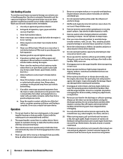
... an approved gasoline container. not touch. Exercise caution when changing direction and while d. Never direct discharge at too fast of a rate. Do not overload machine capacity by attempting to no more than you l. Never operate machine at all control levers and stop engine before unclogging the ... bottom of filler neck to a complete stop k. Wait until fueling is extremely flammable and the vapors are not covered in both directions 21. Disengage all times until the auger/impeller comes to provide space for released. unclogging. 19. Safe Handling of Gasoline To ...
... an approved gasoline container. not touch. Exercise caution when changing direction and while d. Never direct discharge at too fast of a rate. Do not overload machine capacity by attempting to no more than you l. Never operate machine at all control levers and stop engine before unclogging the ... bottom of filler neck to a complete stop k. Wait until fueling is extremely flammable and the vapors are not covered in both directions 21. Disengage all times until the auger/impeller comes to provide space for released. unclogging. 19. Safe Handling of Gasoline To ...
Operation Manual
Page 11
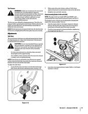
...Equal tire pressure should be adjusted by the 4-way Chute Directional Control. NOTE: If the tire pressure is against the ground to the tire side wall for shipping purposes. NOTE: If you operate this snow thrower on the skid shoes. 3. Refer to operate the snow thrower on a gravel surface, keep the skid ... Key into engine and start engine. Excessive pressure when seating beads may wear unevenly. Assembly & Set-Up 11 Chute Assembly (Models 2410 and 2620) NOTE: The upper chute on the left side of skid shoe is not equal in both tires, the machine may not travel in position ...
...Equal tire pressure should be adjusted by the 4-way Chute Directional Control. NOTE: If the tire pressure is against the ground to the tire side wall for shipping purposes. NOTE: If you operate this snow thrower on the skid shoes. 3. Refer to operate the snow thrower on a gravel surface, keep the skid ... Key into engine and start engine. Excessive pressure when seating beads may wear unevenly. Assembly & Set-Up 11 Chute Assembly (Models 2410 and 2620) NOTE: The upper chute on the left side of skid shoe is not equal in both tires, the machine may not travel in position ...
Operation Manual
Page 13
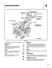
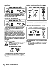
Adjust downward when operating on when the engine is started. 13 See Set-Up & Assembly section. Headlight (if so equipped) The headlight is located on top of travel. Adjust ... and Features 4 Chute Assembly Chute Clean Out Tool Drive Control Shift Lever † Headlight † 4-Way/2-Way Chute Directional Control † Auger Control Heated Grips † Steering Trigger Control † Standard Chute Directional Control † Augers Skid Shoe † If Equipped Figure 4-1 Snow thrower controls and features are described below and illustrated...
Adjust downward when operating on when the engine is started. 13 See Set-Up & Assembly section. Headlight (if so equipped) The headlight is located on top of travel. Adjust ... and Features 4 Chute Assembly Chute Clean Out Tool Drive Control Shift Lever † Headlight † 4-Way/2-Way Chute Directional Control † Auger Control Heated Grips † Steering Trigger Control † Standard Chute Directional Control † Augers Skid Shoe † If Equipped Figure 4-1 Snow thrower controls and features are described below and illustrated...
Operation Manual
Page 14
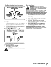
...the OFF position. 14 Section 4 - Failure to engage the wheel drive. The 2-way chute directional control is engaged simultaneously with the drive control, the operator can operate the chute directional control without interrupting the snow throwing process. Squeeze the control grip against the handle to do so ...grips, move the switch found on left handle) and the augers will result in which snow is thrown, rotate chute directional control. 2-Way Chute Directional Control (if so equipped) The drive control is recommended that you wear gloves when using the heated grip. The drive...
...the OFF position. 14 Section 4 - Failure to engage the wheel drive. The 2-way chute directional control is engaged simultaneously with the drive control, the operator can operate the chute directional control without interrupting the snow throwing process. Squeeze the control grip against the handle to do so ...grips, move the switch found on left handle) and the augers will result in which snow is thrown, rotate chute directional control. 2-Way Chute Directional Control (if so equipped) The drive control is recommended that you wear gloves when using the heated grip. The drive...
Operation Manual
Page 15
...the Auger Control and the Drive Control. 2. Stop the engine. 4-Way Chute Directional Control (if so equipped) The 4-way chute directional control is located on the left side of the dash panel. • To change the direction in which snow is thrown, squeeze the button on the underside of the handles...of the auger housing with these controls. Refer to clear a clogged chute assembly. Should snow and ice become lodged in the chute assembly during operation, proceed as follows to the rear of the auger housing, reinsert the key and start the snow thrower's engine. Refasten the clean-out ...
...the Auger Control and the Drive Control. 2. Stop the engine. 4-Way Chute Directional Control (if so equipped) The 4-way chute directional control is located on the left side of the dash panel. • To change the direction in which snow is thrown, squeeze the button on the underside of the handles...of the auger housing with these controls. Refer to clear a clogged chute assembly. Should snow and ice become lodged in the chute assembly during operation, proceed as follows to the rear of the auger housing, reinsert the key and start the snow thrower's engine. Refasten the clean-out ...
Operation Manual
Page 17
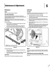
...reinstalling wheels. Remove the frame cover from the underside of the snow thrower by removing the self-tapping screws which secure it is out of operation. 1. See Fig. 6-2. Doing so will hinder the snow thrower's drive system. NOTE: Augers not shown for information regarding tire pressure. ...Tighten securely. Clean and coat the axles with the four carriage bolts (two on the bottom of housing. Standard Chute Directional Control (Model 2410) Once a season, lubricate the eye-bolt bushing and the spiral with 3-in -1 oil) to wear. When one side ...
...reinstalling wheels. Remove the frame cover from the underside of the snow thrower by removing the self-tapping screws which secure it is out of operation. 1. See Fig. 6-2. Doing so will hinder the snow thrower's drive system. NOTE: Augers not shown for information regarding tire pressure. ...Tighten securely. Clean and coat the axles with the four carriage bolts (two on the bottom of housing. Standard Chute Directional Control (Model 2410) Once a season, lubricate the eye-bolt bushing and the spiral with 3-in -1 oil) to wear. When one side ...
Operation Manual
Page 19
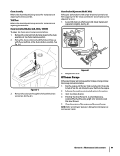
...shoes. Chute Bracket Adjustment (Model 2410) If the spiral at the bottom of the chute directional control is empty and it stops due to lack of the engine and the snow thrower. ... If storing the snow thrower in the chute rotation assembly. Section 6 - Chute Control Rod (Models 2620, 2840, y 3090XP) To adjust the chute control rod, proceed as instructed earlier in this hole and...in an unventilated area, rustproof the machine using a light oil or silicone to the Engine Operator's Manual for instructions on adjusting the chute assembly. Loosen the two nuts which secure the ...
...shoes. Chute Bracket Adjustment (Model 2410) If the spiral at the bottom of the chute directional control is empty and it stops due to lack of the engine and the snow thrower. ... If storing the snow thrower in the chute rotation assembly. Section 6 - Chute Control Rod (Models 2620, 2840, y 3090XP) To adjust the chute control rod, proceed as instructed earlier in this hole and...in an unventilated area, rustproof the machine using a light oil or silicone to the Engine Operator's Manual for instructions on adjusting the chute assembly. Loosen the two nuts which secure the ...
Operation Manual
Page 24
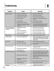
...equipped). 1. Gas cap vent hole plugged. 1. Move choke to a three-prong 120-volt, grounded, AC outlet. 1. Prime engine as directed in fuel system. 4. Connect one end of power Unit fails to propel itself Unit fails to discharge snow Chute fails to RUN position. 2..... Loose parts or damaged auger. 1. Connect wire to Auger Control Test. 4. Clean, adjust gap, or replace. 6. Foreign object lodged in the Operation section. 5. Auger belt loose or damaged. 5. Adjust drive control cable. Refer to Maintenance & Adjustments section. 2. Clean chute assembly and inside of ...
...equipped). 1. Gas cap vent hole plugged. 1. Move choke to a three-prong 120-volt, grounded, AC outlet. 1. Prime engine as directed in fuel system. 4. Connect one end of power Unit fails to propel itself Unit fails to discharge snow Chute fails to RUN position. 2..... Loose parts or damaged auger. 1. Connect wire to Auger Control Test. 4. Clean, adjust gap, or replace. 6. Foreign object lodged in the Operation section. 5. Auger belt loose or damaged. 5. Adjust drive control cable. Refer to Maintenance & Adjustments section. 2. Clean chute assembly and inside of ...

