Service Manual
Page 5
... other terminal of the unit. Figure 1.3 NOTE: In figure 1.3, the meter shows continuity (near 0 ohms). Self-propelled Chipper Shredder Vacuum Self-propelled Chipper Shredder Vacuum ABOUT THIS SECTION: In model year 2000, MTD introduced a vertical crankshaft lawn vacuum with a removable vacuum hose. SAFETY SWITCH The safety switch is located at the bullet connector. 1.3. The switch is in place...
... other terminal of the unit. Figure 1.3 NOTE: In figure 1.3, the meter shows continuity (near 0 ohms). Self-propelled Chipper Shredder Vacuum Self-propelled Chipper Shredder Vacuum ABOUT THIS SECTION: In model year 2000, MTD introduced a vertical crankshaft lawn vacuum with a removable vacuum hose. SAFETY SWITCH The safety switch is located at the bullet connector. 1.3. The switch is in place...
Service Manual
Page 6
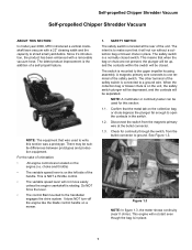
... tab. 1.9. The switch should show continuity with the plunger up , it downward will enable the switch to work correctly. Test the switch independently. Self-propelled Chipper Shredder Vacuum 1.4. Remove the switch from the magneto to ground out the magneto when the plunger is up. Figure 1.6 NOTE: If the switch fails to ground when...
... tab. 1.9. The switch should show continuity with the plunger up , it downward will enable the switch to work correctly. Test the switch independently. Self-propelled Chipper Shredder Vacuum 1.4. Remove the switch from the magneto to ground out the magneto when the plunger is up. Figure 1.6 NOTE: If the switch fails to ground when...
Service Manual
Page 7
... switch works correctly, but does not ground the magneto, the problem lies in bail. See Figure 2.3. Mounting Bolts for full movement. See Figure 2.2. Self-propelled Chipper Shredder Vacuum 1.11.
... switch works correctly, but does not ground the magneto, the problem lies in bail. See Figure 2.3. Mounting Bolts for full movement. See Figure 2.2. Self-propelled Chipper Shredder Vacuum 1.11.
Service Manual
Page 8
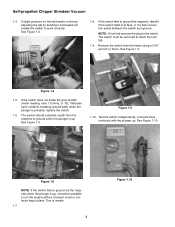
Self-propelled Chipper Shredder Vacuum 2.4. Low speed position: Sheaves together High speed position: Sheaves apart 2.7. See Figure 2.7. If there is routed properly. 2.6. Safety switch Figure 2.6 4 It may be a problem in ...
Self-propelled Chipper Shredder Vacuum 2.4. Low speed position: Sheaves together High speed position: Sheaves apart 2.7. See Figure 2.7. If there is routed properly. 2.6. Safety switch Figure 2.6 4 It may be a problem in ...
Service Manual
Page 9
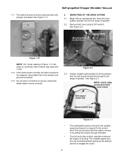
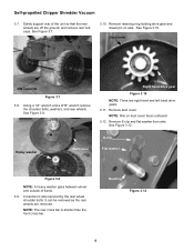
Self-propelled Chipper Shredder Vacuum 2.11. Using a 3/8" socket, remove the 3 self tapping screws securing the belt cover. See Figure 3.4. See Figure 2.12. See Figure 2.11. 3. Right side gear Drive axle ... and an "L" on the correct side. Insert a 3/8" breaker bar and extension into the square hole of the tensioner arm. lead from the spark plug. 3.2. Remove vacuum hose if attached. 3.4. TRANSMISSION REMOVAL 3.1. Figure 3.5 3.6. Remove collection bag or blower chute. 3.3.
Self-propelled Chipper Shredder Vacuum 2.11. Using a 3/8" socket, remove the 3 self tapping screws securing the belt cover. See Figure 3.4. See Figure 2.12. See Figure 2.11. 3. Right side gear Drive axle ... and an "L" on the correct side. Insert a 3/8" breaker bar and extension into the square hole of the tensioner arm. lead from the spark plug. 3.2. Remove vacuum hose if attached. 3.4. TRANSMISSION REMOVAL 3.1. Figure 3.5 3.6. Remove collection bag or blower chute. 3.3.
Service Manual
Page 10
... wheels are removed. See Figure 3.10. It can be removed as the rear wheels are off the ground, and remove rear hub caps. Self-propelled Chipper Shredder Vacuum 3.7. Safely support rear of frame. 3.9. Right hand drive gear Figure 3.10 NOTE: There are right hand and left hand drive gears 3.11. Remove E-clip and...
... wheels are removed. See Figure 3.10. It can be removed as the rear wheels are off the ground, and remove rear hub caps. Self-propelled Chipper Shredder Vacuum 3.7. Safely support rear of frame. 3.9. Right hand drive gear Figure 3.10 NOTE: There are right hand and left hand drive gears 3.11. Remove E-clip and...
Service Manual
Page 11
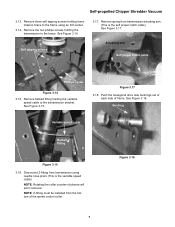
... phillips screws holding the variable speed cable to the transmission bracket. See Figure 3.18. Bushing Variable speed cable Barbed fitting Figure 3.15 3.16. Self-propelled Chipper Shredder Vacuum 3.13. Remove spring from transmission using an 3/8 socket. 3.14. See Figure 3.15. Remove barbed fitting holding the transmission to the frame using needle nose pliers...
... phillips screws holding the variable speed cable to the transmission bracket. See Figure 3.18. Bushing Variable speed cable Barbed fitting Figure 3.15 3.16. Self-propelled Chipper Shredder Vacuum 3.13. Remove spring from transmission using an 3/8 socket. 3.14. See Figure 3.15. Remove barbed fitting holding the transmission to the frame using needle nose pliers...
Service Manual
Page 12
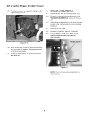
... support the front of this point the transmission will be solely in your hands 3.21. IMPELLER AND BELT REMOVAL 4.1. Remove the hub caps. 4.5. Self-propelled Chipper Shredder Vacuum 3.19. Pivot transmission rearward while sliding it to the right. Self propelled transmission Figure 3.19 3.20. Install new transmission in the TRASMISSION REMOVAL section of...
... support the front of this point the transmission will be solely in your hands 3.21. IMPELLER AND BELT REMOVAL 4.1. Remove the hub caps. 4.5. Self-propelled Chipper Shredder Vacuum 3.19. Pivot transmission rearward while sliding it to the right. Self propelled transmission Figure 3.19 3.20. Install new transmission in the TRASMISSION REMOVAL section of...
Service Manual
Page 13
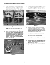
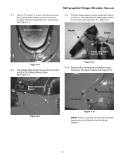
...bolt Lower housing Figure 4.8 Figure 4.10 NOTE: There is a variety of the fasteners holding the two housings together. 9 Self-propelled Chipper Shredder Vacuum 4.7. See Figure 4.9. Remove all of nuts, bolts, and selftapping screws holding the lower housing to the upper housing. Use a 1/4"...nozzle to pass by the hose opening freely. Black plastic nozzle Nozzle Engine 1/4" Screws Figure 4.7 4.8. Remove them. Safety gate within vacuum tube Figure 4.9 4.10. See Figure 4.8. They are accessible from underneath. See Figure 4.10. See Figure 4.7. 4.9. This will ...
...bolt Lower housing Figure 4.8 Figure 4.10 NOTE: There is a variety of the fasteners holding the two housings together. 9 Self-propelled Chipper Shredder Vacuum 4.7. See Figure 4.9. Remove all of nuts, bolts, and selftapping screws holding the lower housing to the upper housing. Use a 1/4"...nozzle to pass by the hose opening freely. Black plastic nozzle Nozzle Engine 1/4" Screws Figure 4.7 4.8. Remove them. Safety gate within vacuum tube Figure 4.9 4.10. See Figure 4.8. They are accessible from underneath. See Figure 4.10. See Figure 4.7. 4.9. This will ...
Service Manual
Page 14
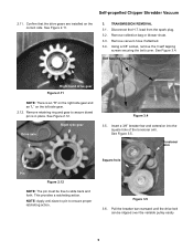
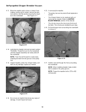
... Figure 4.11. Drive belt Chock Figure 4.11 4.12. Lubricate the impeller removal tool (part number 753-0638). Inspect impeller, pulley hub, chipper blade, and flails for any signs of the manual. • The roll pins secure the clevis pins that shows any damage, replace as ...create slack, releasing the belt from rotating. NOTE: When installing impeller make certain belt is seated in the pulley hub. 4.13. Self-propelled Chipper Shredder Vacuum 4.11. In servicing the impeller: • The pulley hub can be pried off the crankshaft. The roll pins are shielded by pin clips...
... Figure 4.11. Drive belt Chock Figure 4.11 4.12. Lubricate the impeller removal tool (part number 753-0638). Inspect impeller, pulley hub, chipper blade, and flails for any signs of the manual. • The roll pins secure the clevis pins that shows any damage, replace as ...create slack, releasing the belt from rotating. NOTE: When installing impeller make certain belt is seated in the pulley hub. 4.13. Self-propelled Chipper Shredder Vacuum 4.11. In servicing the impeller: • The pulley hub can be pried off the crankshaft. The roll pins are shielded by pin clips...
Service Manual
Page 15
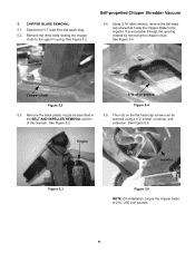
... 5.1. See Figure 5.4. See Figure 5.5. Engine Impeller Figure 5.3 Figure 5.5 NOTE: On installation, torque the chipper blade to the upper housing. Remove the three bolts holding the chipper chute to 210 - 250 inch pounds. 11 Self-propelled Chipper Shredder Vacuum 5.4. Chipper chute Figure 5.2 5.3. The nuts on the flat head cap screws can be reached using a 1/2" socket, universal, and...
... 5.1. See Figure 5.4. See Figure 5.5. Engine Impeller Figure 5.3 Figure 5.5 NOTE: On installation, torque the chipper blade to the upper housing. Remove the three bolts holding the chipper chute to 210 - 250 inch pounds. 11 Self-propelled Chipper Shredder Vacuum 5.4. Chipper chute Figure 5.2 5.3. The nuts on the flat head cap screws can be reached using a 1/2" socket, universal, and...


