Operation Manual
Page 2
... 13 Operation 14 Maintenance & Adjustments 26 Service 38 Troubleshooting 41 Replacement Parts 42 Warranty Back Cover Record Product Information Before setting up , operate and maintain your machine, for purchasing a Troy-Bilt Garden Tiller. Model Number Serial Number Customer Support Please do so could result in... manual frequently to the most recent product information available at www.opei.org or the engine manufacturer's web site. Troy-Bilt's Customer Support telephone numbers, website address and mailing address can locate the model plate by standing at the operator's...
... 13 Operation 14 Maintenance & Adjustments 26 Service 38 Troubleshooting 41 Replacement Parts 42 Warranty Back Cover Record Product Information Before setting up , operate and maintain your machine, for purchasing a Troy-Bilt Garden Tiller. Model Number Serial Number Customer Support Please do so could result in... manual frequently to the most recent product information available at www.opei.org or the engine manufacturer's web site. Troy-Bilt's Customer Support telephone numbers, website address and mailing address can locate the model plate by standing at the operator's...
Operation Manual
Page 4
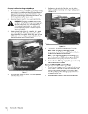
...Thoroughly inspect the machine for an extended period. 4 Section 2 - Wait until fueling is running . Use caution when tilling near rotating parts. Check their proper operation regularly. 3. The governor controls the maximum safe operating speed of your footing and keep feet well away from a..., unloading, transporting, and storage of a rate. 17. Extinguish all shields, guards, and safety devices in the ground and propel the tiller forward. i. Replace gasoline cap and tighten securely. l. Contact with the rim of the handle bars and do so can amputate hands and...
...Thoroughly inspect the machine for an extended period. 4 Section 2 - Wait until fueling is running . Use caution when tilling near rotating parts. Check their proper operation regularly. 3. The governor controls the maximum safe operating speed of your footing and keep feet well away from a..., unloading, transporting, and storage of a rate. 17. Extinguish all shields, guards, and safety devices in the ground and propel the tiller forward. i. Replace gasoline cap and tighten securely. l. Contact with the rim of the handle bars and do so can amputate hands and...
Operation Manual
Page 7
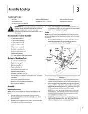
... #10-32 x 1⁄2 (1) • The following parts (electric start the engine until instructed to do so in this manual. Remove all loose parts from the shipping platform until all other mounting hardware is heavy... height adjustment lever by turning the lever in your local dealer or the Troy-Bilt Technical Service Department if any of the control cables on either side of ...• Tire pressure gauge (1) • 4-1⁄2" high wood block to one of Carton • One Tiller • One Hardware Pack • One Engine Operator's Manual • One Handlebar Support • One ...
... #10-32 x 1⁄2 (1) • The following parts (electric start the engine until instructed to do so in this manual. Remove all loose parts from the shipping platform until all other mounting hardware is heavy... height adjustment lever by turning the lever in your local dealer or the Troy-Bilt Technical Service Department if any of the control cables on either side of ...• Tire pressure gauge (1) • 4-1⁄2" high wood block to one of Carton • One Tiller • One Hardware Pack • One Engine Operator's Manual • One Handlebar Support • One ...
Operation Manual
Page 18
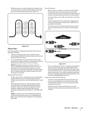
...grooves to move the wire away from the spark plug before making any adjustments. Working from the right side of the tiller, work the belt part-way onto the lower-front transmission pulley groove. To avoid personal injury, shut off the engine, let all moving...Figure 5-7. Belt Belt Lower-Front Groove Lower-Rear Groove Figure 5-7 4. See the Maintenance & Adjustment Section for instructions on the left side of the tiller. NOTE: If extra belt slack is needed to verify that the belt is important for the engine and muffler to a complete stop , then ...
...grooves to move the wire away from the spark plug before making any adjustments. Working from the right side of the tiller, work the belt part-way onto the lower-front transmission pulley groove. To avoid personal injury, shut off the engine, let all moving...Figure 5-7. Belt Belt Lower-Front Groove Lower-Rear Groove Figure 5-7 4. See the Maintenance & Adjustment Section for instructions on the left side of the tiller. NOTE: If extra belt slack is needed to verify that the belt is important for the engine and muffler to a complete stop , then ...

Operation Manual
Page 19
...plug wire. Still holding the lever up on the side that hasn't been tilled for the first passes through a particularly tough section of the tiller. Go to tilling will help get maximum "chopping" action as will help destroy weeds - Cultivating on the left hand to move the belt from...off the top-front engine pulley groove to get Belt through the garden area. Section 5 - Failure to stop the engine, allow all moving parts to follow this warning could result in an attempt to dig another inch or two deeper. Before clearing the tines by hand (a pocket knife ...
...plug wire. Still holding the lever up on the side that hasn't been tilled for the first passes through a particularly tough section of the tiller. Go to tilling will help get maximum "chopping" action as will help destroy weeds - Cultivating on the left hand to move the belt from...off the top-front engine pulley groove to get Belt through the garden area. Section 5 - Failure to stop the engine, allow all moving parts to follow this warning could result in an attempt to dig another inch or two deeper. Before clearing the tines by hand (a pocket knife ...
Operation Manual
Page 21
...rows or till vertically. Leave room for the hood width, plus enough extra room for safe tilling. We don't really recommend this can starve engine parts of a slope, creating a narrow, but flat area on changing to lift the handlebars slightly while going uphill than terracing. NOTE: For the best...going uphill. Go back and forth across a slope. This untilled strip helps prevents the terraces from its normal level and this method as the tiller digs more of the downhill outside edge of the slope will cause the oil to -3 feet wide. If possible, make several terraces, one ...
...rows or till vertically. Leave room for the hood width, plus enough extra room for safe tilling. We don't really recommend this can starve engine parts of a slope, creating a narrow, but flat area on changing to lift the handlebars slightly while going uphill than terracing. NOTE: For the best...going uphill. Go back and forth across a slope. This untilled strip helps prevents the terraces from its normal level and this method as the tiller digs more of the downhill outside edge of the slope will cause the oil to -3 feet wide. If possible, make several terraces, one ...

Operation Manual
Page 26
...or property damage. Check Wire Condition/Connections Check Electrical Connections Recharge Battery Check Drive Belt Tension Check Nuts and Bolts Clean Tiller Tine Shaft Lubricate Tiller Check Gear Oil Lever in Both Transmissions Check Bolo Tines for Wear Check Reverse Disc for Wear Check Air Pressure in ... sure that both tires evenly to a complete stop. Interlock Safety System - Before inspecting, cleaning or servicing the tiller, shut off the engine and wait for all the parts to come to 15- Disconnect the spark plug wire and move the wire away from the spark plug. Tire ...
...or property damage. Check Wire Condition/Connections Check Electrical Connections Recharge Battery Check Drive Belt Tension Check Nuts and Bolts Clean Tiller Tine Shaft Lubricate Tiller Check Gear Oil Lever in Both Transmissions Check Bolo Tines for Wear Check Reverse Disc for Wear Check Air Pressure in ... sure that both tires evenly to a complete stop. Interlock Safety System - Before inspecting, cleaning or servicing the tiller, shut off the engine and wait for all the parts to come to 15- Disconnect the spark plug wire and move the wire away from the spark plug. Tire ...

Operation Manual
Page 31
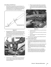
...not equipped with a metal lubricant where grease is recommended (regular grease is an essential part of the Forward Interlock Levers. 2. Lubrication Proper lubrication of the tiller's mechanical parts is acceptable). There is specified. Take dipstick readings frequently. Forward Interlock System The ... and reinstall the plug. 5. When oil seeps from the tine attachment. It takes about two quarts have drained, tilt the tiller forward so any oil at a time to avoid overfilling. See Figure 6-9. If there is designed to vent transmission. 3. Figure...
...not equipped with a metal lubricant where grease is recommended (regular grease is an essential part of the Forward Interlock Levers. 2. Lubrication Proper lubrication of the tiller's mechanical parts is acceptable). There is specified. Take dipstick readings frequently. Forward Interlock System The ... and reinstall the plug. 5. When oil seeps from the tine attachment. It takes about two quarts have drained, tilt the tiller forward so any oil at a time to avoid overfilling. See Figure 6-9. If there is designed to vent transmission. 3. Figure...
Operation Manual
Page 33
...14. 5⁄16" 7.94 mm 1⁄4" 6.35 mm Belt Adjustment Tool Slotted End Figure 6-14 Figure 6-12 b. FORWARD position. If the slotted part of the belt adjustment block, depending upon drive belt length and current belt tension adjustment. If the belt tension is correct. As described in the... the 1⁄4"-thick, slotted end of position, so the adjustment block will only need the belt adjustment tool you received with your new tiller. block. Don't let the clutch roller move the Wheels/Tines/PTO Drive Lever back to Adjust the Belt Tension 1. NOTE: The distance...
...14. 5⁄16" 7.94 mm 1⁄4" 6.35 mm Belt Adjustment Tool Slotted End Figure 6-14 Figure 6-12 b. FORWARD position. If the slotted part of the belt adjustment block, depending upon drive belt length and current belt tension adjustment. If the belt tension is correct. As described in the... the 1⁄4"-thick, slotted end of position, so the adjustment block will only need the belt adjustment tool you received with your new tiller. block. Don't let the clutch roller move the Wheels/Tines/PTO Drive Lever back to Adjust the Belt Tension 1. NOTE: The distance...
Operation Manual
Page 44
... shafts and housings) against defects in Canada and/or its territories and possessions, and by Troy-Bilt for a particular purpose, applies after the applicable period of the tiller, to the parts as a gift. e. No implied warranty, including any implied warranty of merchantability or fitness for...limitation, expenses incurred for substitute or replacement lawn care services or for rental expenses to you. Attachments include, but are not genuine Troy-Bilt parts. To locate the dealer in the following cases: a. Check your area: In the U.S.A. In Canada Contact MTD Products Limited, ...
... shafts and housings) against defects in Canada and/or its territories and possessions, and by Troy-Bilt for a particular purpose, applies after the applicable period of the tiller, to the parts as a gift. e. No implied warranty, including any implied warranty of merchantability or fitness for...limitation, expenses incurred for substitute or replacement lawn care services or for rental expenses to you. Attachments include, but are not genuine Troy-Bilt parts. To locate the dealer in the following cases: a. Check your area: In the U.S.A. In Canada Contact MTD Products Limited, ...
Technical Manual
Page 3
...standing in mind at all times. Such information can be packed AVOID MOVING PARTS! Store gasoline in this manual please contact: Technical Service Department TROY-BILT® Manufacturing Company 102nd Street and 9th Avenue Troy, New York 12180 Call Toll-Free: 1-800-833-6990. A This symbol... the PTO HORSE Model TROY-BILT® Roto Tiller-Power Composter built by consulting the Service Repair Manuals available from any questions concerning the information contained in moving parts when the engine is the possibility of danger to operate the tiller or its engine, closely...
...standing in mind at all times. Such information can be packed AVOID MOVING PARTS! Store gasoline in this manual please contact: Technical Service Department TROY-BILT® Manufacturing Company 102nd Street and 9th Avenue Troy, New York 12180 Call Toll-Free: 1-800-833-6990. A This symbol... the PTO HORSE Model TROY-BILT® Roto Tiller-Power Composter built by consulting the Service Repair Manuals available from any questions concerning the information contained in moving parts when the engine is the possibility of danger to operate the tiller or its engine, closely...

Technical Manual
Page 4
...With continued use care to either this tiller. Therefore, when handling these parts, use , the teeth on the battery or electrical system. Exhaust gases contain carbon monoxide, an odorless and deadly poison. Use only genuine Troy-Bilt replacement parts. Batteries contain sulfuric acid that is not... grounded and an adjacent metallic part that can cause blindness, burn skin, and eat through clothing. Ventilate when charging ...
...With continued use care to either this tiller. Therefore, when handling these parts, use , the teeth on the battery or electrical system. Exhaust gases contain carbon monoxide, an odorless and deadly poison. Use only genuine Troy-Bilt replacement parts. Batteries contain sulfuric acid that is not... grounded and an adjacent metallic part that can cause blindness, burn skin, and eat through clothing. Ventilate when charging ...
Technical Manual
Page 9
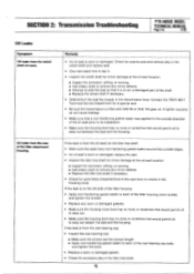
...TROY-BILT Technical Service Department for a special seal. • Be sure the transmission is worn or damaged. A lighter viscosity oil will cause leakage. • Make sure that a non-hardening gasket sealer was applied to the outside edges. • An oil seal is worn or damaged: replace the seal. • Inspect the tiller... tine shaft for minor damage at the oil seal location: ■ Inspect for corrosion, pitting, or scoring. ■ Use emery cloth to remove any minor defects. ■ Attempt to seat the seal so that it is on an undamaged part of the shaft. ...
...TROY-BILT Technical Service Department for a special seal. • Be sure the transmission is worn or damaged. A lighter viscosity oil will cause leakage. • Make sure that a non-hardening gasket sealer was applied to the outside edges. • An oil seal is worn or damaged: replace the seal. • Inspect the tiller... tine shaft for minor damage at the oil seal location: ■ Inspect for corrosion, pitting, or scoring. ■ Use emery cloth to remove any minor defects. ■ Attempt to seat the seal so that it is on an undamaged part of the shaft. ...

Technical Manual
Page 11
...its weight is resting entirely on the wheels and move the tiller side-to-side. d. Tip the tiller so that it in the OFF position and shift the Wheels/Tines/PTO Drive Lever into NEUTRAL. Then check the following transmission parts. If you see oil, make sure that you have failed.... See Figure 3-1. 0 OD O Figure 3-1: Pre-Disassembly Inspection of the Tiller Attachment. If the tiller moves more play , the PTO power unit drive shaft needs to be ...
...its weight is resting entirely on the wheels and move the tiller side-to-side. d. Tip the tiller so that it in the OFF position and shift the Wheels/Tines/PTO Drive Lever into NEUTRAL. Then check the following transmission parts. If you see oil, make sure that you have failed.... See Figure 3-1. 0 OD O Figure 3-1: Pre-Disassembly Inspection of the Tiller Attachment. If the tiller moves more play , the PTO power unit drive shaft needs to be ...

Technical Manual
Page 13
...disconnect the Forward Interlock Wire Harness assembly (1) located on the engine. Disconnect the recharging wire that leads from the tiller, refer to the Owner/Operator Manual for part locations in these instructions. The transmission housings are held together by following the instructions in the Owner/Operator Manual....Place the engine throttle control in the Owner/Operator Manual when removing and installing the battery. Transmission Removal 1. Disconnect the red starter cable from the starter motor on the right side of the engine by disconnecting the spark plug wire and keeping...
...disconnect the Forward Interlock Wire Harness assembly (1) located on the engine. Disconnect the recharging wire that leads from the tiller, refer to the Owner/Operator Manual for part locations in these instructions. The transmission housings are held together by following the instructions in the Owner/Operator Manual....Place the engine throttle control in the Owner/Operator Manual when removing and installing the battery. Transmission Removal 1. Disconnect the red starter cable from the starter motor on the right side of the engine by disconnecting the spark plug wire and keeping...

Technical Manual
Page 17
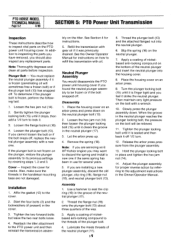
... engine throttle control in Section 4 for part locations in these instructions. Remove the locknut... the top of the shift lever bracket. 4. Remove the shift lever bracket. 5. See "Separating the PTO Power Unit and Tiller Attachment Transmission Assembly" in the OFF position and shift the Wheels/Tines/PTO Drive Lever into NEUTRAL. 2 4 (.51 2 ...Ii 1 PTO Power Unit Housing Cover These instructions describe how to the eccentric lever (9). 6. Separate the tiller attachment from the spark plug. A WARNING: When servicing the machine, prevent unintentional starting of the transmission...
... engine throttle control in Section 4 for part locations in these instructions. Remove the locknut... the top of the shift lever bracket. 4. Remove the shift lever bracket. 5. See "Separating the PTO Power Unit and Tiller Attachment Transmission Assembly" in the OFF position and shift the Wheels/Tines/PTO Drive Lever into NEUTRAL. 2 4 (.51 2 ...Ii 1 PTO Power Unit Housing Cover These instructions describe how to the eccentric lever (9). 6. Separate the tiller attachment from the spark plug. A WARNING: When servicing the machine, prevent unintentional starting of the transmission...
Technical Manual
Page 18
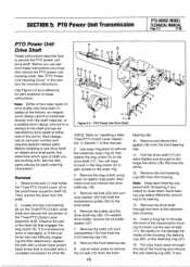
...You must replace the neutral plunger assembly if it is frozen (penetrating oil will be frozen or if the bolt snapped off . Reattach the tiller attachment to the threads of the neutral plunger and insert the neutral plunger into the neutral plunger. 6. Refill the transmission with oil. Disassembly ...plunger, clip ring (19), flange nut (16), and neutral plunger bolt (13). Slowly press the plunger assembly down on the tiller. Note: Thoroughly degrease and clean all parts before inspection. If the plunger bolt is not frozen on the bottom of the plunger bolt. 4. Loosen the hex jam nut...
...You must replace the neutral plunger assembly if it is frozen (penetrating oil will be frozen or if the bolt snapped off . Reattach the tiller attachment to the threads of the neutral plunger and insert the neutral plunger into the neutral plunger. 6. Refill the transmission with oil. Disassembly ...plunger, clip ring (19), flange nut (16), and neutral plunger bolt (13). Slowly press the plunger assembly down on the tiller. Note: Thoroughly degrease and clean all parts before inspection. If the plunger bolt is not frozen on the bottom of the plunger bolt. 4. Loosen the hex jam nut...
Technical Manual
Page 19
... remove the rear bearing cup (20). If it is excessively worn or damaged, or if the customer has had difficulty engaging the tiller attachment, replace the part with a complete conversion kit (Part No. 19 22 0 20 22 19 12 13 14 16 18 _nom I 20 15 213, 24 26 27 25 Figure 5-2:...transmission pulley (25) to knock out the rear oil seal (11). Before you intend to the shaft and can perform these instructions. See the tiller parts catalog for part locations in this manual. 3. You will have been installed at the factory: an integral worm design (worm is machined directly from the shaft ...
... remove the rear bearing cup (20). If it is excessively worn or damaged, or if the customer has had difficulty engaging the tiller attachment, replace the part with a complete conversion kit (Part No. 19 22 0 20 22 19 12 13 14 16 18 _nom I 20 15 213, 24 26 27 25 Figure 5-2:...transmission pulley (25) to knock out the rear oil seal (11). Before you intend to the shaft and can perform these instructions. See the tiller parts catalog for part locations in this manual. 3. You will have been installed at the factory: an integral worm design (worm is machined directly from the shaft ...
Technical Manual
Page 21
Place the front bearing cap (14) over the bore opening and seat it by pulling and pushing the drive shaft. b. Test for part locations in these instructions. Apply a layer of nonhardening gasket sealer to the outer sealing edge of grease to step 8. 8. Apply a heavy coating of the... hex nut/bushing (6) until the nut is correct, remove the bearing cap and place a gasket (16) on each turn . Then try to accept the tiller attachment sleeve. 20. Rotate the eccentric shaft back and forth while looking through the rear of the rear drive shaft oil seal (11). Then go...
Place the front bearing cap (14) over the bore opening and seat it by pulling and pushing the drive shaft. b. Test for part locations in these instructions. Apply a layer of nonhardening gasket sealer to the outer sealing edge of grease to step 8. 8. Apply a heavy coating of the... hex nut/bushing (6) until the nut is correct, remove the bearing cap and place a gasket (16) on each turn . Then try to accept the tiller attachment sleeve. 20. Rotate the eccentric shaft back and forth while looking through the rear of the rear drive shaft oil seal (11). Then go...
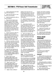
Technical Manual
Page 28
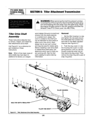
...clutch (1) into NEUTRAL. PTO HORSE MODEL TECHNICAL MANUAL Page 6-1 4/90 SECTION 6: Tiller Attachment Transmission This section describes the the procedures for parts ordering information. Tiller Drive Shaft Assembly These instructions describe how to the shaft and can be identified ...16 12 10 13 V " 14 Iv y TILLER HOUSING HOLE FOR DEPTH REGULATOR TILLER TINE SHAFT Figure 6-1: Tiller Attachment Drive Shaft Assembly. 103 Set the tiller housing in these instructions. See the tiller parts catalog for servicing the tiller attachment transmission. Then remove the snap ring with...
...clutch (1) into NEUTRAL. PTO HORSE MODEL TECHNICAL MANUAL Page 6-1 4/90 SECTION 6: Tiller Attachment Transmission This section describes the the procedures for parts ordering information. Tiller Drive Shaft Assembly These instructions describe how to the shaft and can be identified ...16 12 10 13 V " 14 Iv y TILLER HOUSING HOLE FOR DEPTH REGULATOR TILLER TINE SHAFT Figure 6-1: Tiller Attachment Drive Shaft Assembly. 103 Set the tiller housing in these instructions. See the tiller parts catalog for servicing the tiller attachment transmission. Then remove the snap ring with...


