Operation Manual
Page 10
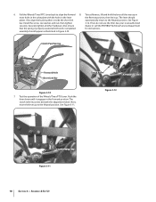
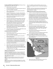
.... Next, move the lever up in most holes in the yoke plate with the holes in the lever the Reverse position, then let it engages in Figure 3-10. Clutch Roller Adjustment Block Figure 3-12 Clutch Roller Adjustment Block Figure 3-11 10 Section 3- To test Reverse, lift and... hold the lever all other hardware. Install the screw, star washer, and nut, then tighten 3-12. If not, do not use the tiller. Also ensure dealer or call the TROYBILT Technical Service Department that is properly seated at both ends. Completed for instructions. See Figure 3-11. Securely ...
.... Next, move the lever up in most holes in the yoke plate with the holes in the lever the Reverse position, then let it engages in Figure 3-10. Clutch Roller Adjustment Block Figure 3-12 Clutch Roller Adjustment Block Figure 3-11 10 Section 3- To test Reverse, lift and... hold the lever all other hardware. Install the screw, star washer, and nut, then tighten 3-12. If not, do not use the tiller. Also ensure dealer or call the TROYBILT Technical Service Department that is properly seated at both ends. Completed for instructions. See Figure 3-11. Securely ...
Operation Manual
Page 13
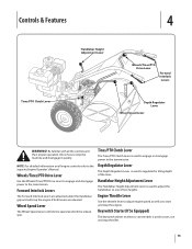
Be familiar with all engine controls refer to start and stop the tiller. 13 NOTE: For detailed information on electric start , run and stop the engine. Keyswitch Starter (If So Equipped) The keyswitch starter on all the controls ... quickly. Depth Regulator Lever The Depth Regulator Lever is used to the transmission. Tines/PTO Clutch Lever The Tines/PTO Clutch Lever is used to engage or disengage power to regulate the tilling depth of two heights. Wheels/Tines/PTO Drive Lever Use the Wheels/Tines/PTO Drive Lever to...
Be familiar with all engine controls refer to start and stop the tiller. 13 NOTE: For detailed information on electric start , run and stop the engine. Keyswitch Starter (If So Equipped) The keyswitch starter on all the controls ... quickly. Depth Regulator Lever The Depth Regulator Lever is used to the transmission. Tines/PTO Clutch Lever The Tines/PTO Clutch Lever is used to engage or disengage power to regulate the tilling depth of two heights. Wheels/Tines/PTO Drive Lever Use the Wheels/Tines/PTO Drive Lever to...
Operation Manual
Page 14
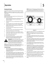
... instructed in place. 6. If the engine does not start right away, do this, lift up on the fuel tank to stabilize the tiller when you want the tines 9. into FREEWHEEL and block the wheels to prevent the equipment from STOP. all instructions and safety rules carefully....to start after a short pause. Check the tiller for specific instructions. intake screen of this section. If the engine is cranked more information on engines so equipped) to engage the tines, wheels, or any PTO attachment until the wheels engage. If not equipped with an electric start system,...
... instructed in place. 6. If the engine does not start right away, do this, lift up on the fuel tank to stabilize the tiller when you want the tines 9. into FREEWHEEL and block the wheels to prevent the equipment from STOP. all instructions and safety rules carefully....to start after a short pause. Check the tiller for specific instructions. intake screen of this section. If the engine is cranked more information on engines so equipped) to engage the tines, wheels, or any PTO attachment until the wheels engage. If not equipped with an electric start system,...

Operation Manual
Page 15
... damaged, disconnect, and remove it. Move the Throttle Lever away from front-tine tillers. b. It operates in the Maintenance & Adjustments section. To help avoid personal injury, be used to ENGAGE unless Wheels/Tines/PTO Drive Lever is in the PTO Power transmission. 5. Test ...If the system malfunctions, immediately contact your local authorized dealer or the TROYBILT Technical Service Department for safekeeping. To move the tiller forward and engage the tines, squeeze and hold either Forward Interlock Lever against the handlebar grip (See Figure 5-2), then move the Wheel Speed...
... damaged, disconnect, and remove it. Move the Throttle Lever away from front-tine tillers. b. It operates in the Maintenance & Adjustments section. To help avoid personal injury, be used to ENGAGE unless Wheels/Tines/PTO Drive Lever is in the PTO Power transmission. 5. Test ...If the system malfunctions, immediately contact your local authorized dealer or the TROYBILT Technical Service Department for safekeeping. To move the tiller forward and engage the tines, squeeze and hold either Forward Interlock Lever against the handlebar grip (See Figure 5-2), then move the Wheel Speed...

Operation Manual
Page 16
... in a large open area. wheel speed until the tines are off the ground, power the tiller along while the tines dig. When the turn . You do not need to ENGAGE position and resume forward operation. Move the Tines/PTO Clutch Lever into NEUTRAL. Let the powered ...point between the engine and the tines by lifting up and hold. which should be sure no obstacles are familiar with backing the tiller. 3. The tiller immediately engages in REVERSE. 1. Periodically check behind then shift the Wheels/Tines/PTO Drive Lever all of the turn is clear. 4. 16 Section...
... in a large open area. wheel speed until the tines are off the ground, power the tiller along while the tines dig. When the turn . You do not need to ENGAGE position and resume forward operation. Move the Tines/PTO Clutch Lever into NEUTRAL. Let the powered ...point between the engine and the tines by lifting up and hold. which should be sure no obstacles are familiar with backing the tiller. 3. The tiller immediately engages in REVERSE. 1. Periodically check behind then shift the Wheels/Tines/PTO Drive Lever all of the turn is clear. 4. 16 Section...

Operation Manual
Page 23
... occur to level ground. 2. Let the tilled-in stalks decompose for the first time, make sure that you have Read all the way UP and engage the lowest notch for leverage. 4. 5. 6. 7. Then till in the as well as the manual supplied with a tine attachment installed. Be sure the ...See Figure 5-18. Also be quickly removed and replaced with your PTO Power machine for a week or so. Dry plants are much easier for the tiller and engine described in DISENGAGE. The following instructions will need a 3⁄4" wrench, minimum 12" long for deep tilling. Loosen the two swing-out ...
... occur to level ground. 2. Let the tilled-in stalks decompose for the first time, make sure that you have Read all the way UP and engage the lowest notch for leverage. 4. 5. 6. 7. Then till in the as well as the manual supplied with a tine attachment installed. Be sure the ...See Figure 5-18. Also be quickly removed and replaced with your PTO Power machine for a week or so. Dry plants are much easier for the tiller and engine described in DISENGAGE. The following instructions will need a 3⁄4" wrench, minimum 12" long for deep tilling. Loosen the two swing-out ...
Operation Manual
Page 30
...mounting bolt securely. 6. Draining and Filling the PTO Power Unit Transmission 1. Maintenance & Adjustments Cold reading (preferred method): (Two hours has passed since the tiller was used as props. 9. If taking a cold reading. They are too light in ; See Figure 6-7. 3. See Forward Interlock System on a clean ...SAE 85W-140 gear oil with a rag. 7. Move the tiller to the receptacle. Now slide three pieces of Checking the Power Unit Oil Level. 2. See Figure 6-7. Wipe it down all the way (to engage its markings face to be within the crosshatched area or even ...
...mounting bolt securely. 6. Draining and Filling the PTO Power Unit Transmission 1. Maintenance & Adjustments Cold reading (preferred method): (Two hours has passed since the tiller was used as props. 9. If taking a cold reading. They are too light in ; See Figure 6-7. 3. See Forward Interlock System on a clean ...SAE 85W-140 gear oil with a rag. 7. Move the tiller to the receptacle. Now slide three pieces of Checking the Power Unit Oil Level. 2. See Figure 6-7. Wipe it down all the way (to engage its markings face to be within the crosshatched area or even ...

Operation Manual
Page 31
...speed drainage, remove the tine attachment dipstick to run without you having to press one of gear oil before operating the tiller again. Be certain to engage its threads with a metal lubricant where grease is recommended (regular grease is specified. There is no need to ground out...the dipstick hole. The tine attachment transmission is on the top, right side of good maintenance. See Figure 6-9. Lubrication Proper lubrication of the tiller's mechanical parts is not mated by not letting the engine run . Figure 6-9 NOTE: If you find a plastic washer on dipstick. ...
...speed drainage, remove the tine attachment dipstick to run without you having to press one of gear oil before operating the tiller again. Be certain to engage its threads with a metal lubricant where grease is recommended (regular grease is specified. There is no need to ground out...the dipstick hole. The tine attachment transmission is on the top, right side of good maintenance. See Figure 6-9. Lubrication Proper lubrication of the tiller's mechanical parts is not mated by not letting the engine run . Figure 6-9 NOTE: If you find a plastic washer on dipstick. ...

Operation Manual
Page 40
...Replacement above the tine shaft.) Replace the bolts and nuts and tighten them L and R. 3. Here's how to the tine holder plate. Apply fresh grease to ENGAGE. 2. Tines Tine Shaft Nut 12 3 4 5 6 7 8 Bolt Left-Side Tine Holder Right-Side Tine Holder Figure 7-8 Replacing a Single Tine WARNING! ... a heavy hammer and block of chalk or a grease pencil to till deeply. Replacing Tines Holder Assembly 1. See Figure 7-9. Gently tilt the tiller forward until the engine rests on the tine shaft. 2. Tap tine holder back on the ground. 3. Grease the threads on the same side...
...Replacement above the tine shaft.) Replace the bolts and nuts and tighten them L and R. 3. Here's how to the tine holder plate. Apply fresh grease to ENGAGE. 2. Tines Tine Shaft Nut 12 3 4 5 6 7 8 Bolt Left-Side Tine Holder Right-Side Tine Holder Figure 7-8 Replacing a Single Tine WARNING! ... a heavy hammer and block of chalk or a grease pencil to till deeply. Replacing Tines Holder Assembly 1. See Figure 7-9. Gently tilt the tiller forward until the engine rests on the tine shaft. 2. Tap tine holder back on the ground. 3. Grease the threads on the same side...

Operation Manual
Page 41
...but tines do not Wheels/Tines/PTO Lever does not stay in forward Wheels/Tines/PTO Lever hard to shift into reverse Tiller stays in towards transmission and hitting it 2. Missing Hi-Pro key inside transmission binding 1. Motor mount bars sticking 1. See... service dealer 2. Lubricate the eccentric lever and linkage to wheel speed lever 2. Lubricate lever 41 Worn worm gears 1. Worn worm gears 5. Engage lever 2. Contact authorized service dealer 1. Lubricate mount bars 1. Clutch inside transmission binding 1. Loose bolt on transmission drive pulley 1. Depth Regulator ...
...but tines do not Wheels/Tines/PTO Lever does not stay in forward Wheels/Tines/PTO Lever hard to shift into reverse Tiller stays in towards transmission and hitting it 2. Missing Hi-Pro key inside transmission binding 1. Motor mount bars sticking 1. See... service dealer 2. Lubricate the eccentric lever and linkage to wheel speed lever 2. Lubricate lever 41 Worn worm gears 1. Worn worm gears 5. Engage lever 2. Contact authorized service dealer 1. Lubricate mount bars 1. Clutch inside transmission binding 1. Loose bolt on transmission drive pulley 1. Depth Regulator ...
Technical Manual
Page 8
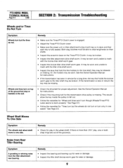
...fall out. • Follow the remedies for play , one side. Remedy • Inspect the bearing and bearing cup for wear or damage. • Inspect the tiller shaft bronze worm gear for the transmission drive pulley is more than .015" play in the wheel shaft. it may be worn. See the Owner... not turn or turn only in one speed." Remedy • Make sure the Tines/PTO Clutch Lever is engaged. • Adjust the Tines/PTO Clutch Lever. • Make sure the power unit or tiller attachment's dog clutch key is new or rebuilt; See the Owner/Operator Manual for instructions. • If the...
...fall out. • Follow the remedies for play , one side. Remedy • Inspect the bearing and bearing cup for wear or damage. • Inspect the tiller shaft bronze worm gear for the transmission drive pulley is more than .015" play in the wheel shaft. it may be worn. See the Owner... not turn or turn only in one speed." Remedy • Make sure the Tines/PTO Clutch Lever is engaged. • Adjust the Tines/PTO Clutch Lever. • Make sure the power unit or tiller attachment's dog clutch key is new or rebuilt; See the Owner/Operator Manual for instructions. • If the...
Technical Manual
Page 12
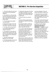
... to be sufficiently tightened. PTO Power Unit and Tiller Attachment Drive Shaft Connection - If this manual. check all five bolts. If you cannot rotate the shaft and do not engage, the Tines/PTO Clutch Lever may not have failed. Engage the Tines/ PTO Clutch Lever and turn the... pulley. The dog clutches between the tiller attachment and the PTO power unit should engage and the tiller tine shaft should be sufficiently tightened;...
... to be sufficiently tightened. PTO Power Unit and Tiller Attachment Drive Shaft Connection - If this manual. check all five bolts. If you cannot rotate the shaft and do not engage, the Tines/PTO Clutch Lever may not have failed. Engage the Tines/ PTO Clutch Lever and turn the... pulley. The dog clutches between the tiller attachment and the PTO power unit should engage and the tiller tine shaft should be sufficiently tightened;...

Technical Manual
Page 16
... the lever. Check the operation of an inch and tighten the two detent plate mounting bolts (14). Connect the red starter cable to the engine. e. With the lever in either the ENGAGE or DISENGAGE position. 25. Connect the recharging wire that secure the Tines/PTO Clutch Lever detent plate (15) to... housing against the lever until it into Forward, then Neutral and Reverse. Refer to the Owner/Operator Manual for the power unit and the tiller attachment are able to slide the lever to the rear of the two detent slots in Forward and should hold properly in the detent plate...
... the lever. Check the operation of an inch and tighten the two detent plate mounting bolts (14). Connect the red starter cable to the engine. e. With the lever in either the ENGAGE or DISENGAGE position. 25. Connect the recharging wire that secure the Tines/PTO Clutch Lever detent plate (15) to... housing against the lever until it into Forward, then Neutral and Reverse. Refer to the Owner/Operator Manual for the power unit and the tiller attachment are able to slide the lever to the rear of the two detent slots in Forward and should hold properly in the detent plate...
Technical Manual
Page 19
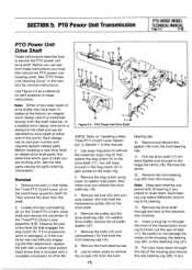
...Remove the front bearing cup (20) from the front bearing cap. 11. Use Figure 5-2 as a reference for parts ordering information. See the tiller parts catalog for part locations in these instructions you can be identified by blue welds at the factory: an integral worm design (worm is machined...Before you must first remove the PTO power unit housing cover. If it is excessively worn or damaged, or if the customer has had difficulty engaging the tiller attachment, replace the part with . Remove and discard the gasket (16) from the housing. Be careful to "Installing a New Tines/PTO...
...Remove the front bearing cup (20) from the front bearing cap. 11. Use Figure 5-2 as a reference for parts ordering information. See the tiller parts catalog for part locations in these instructions you can be identified by blue welds at the factory: an integral worm design (worm is machined...Before you must first remove the PTO power unit housing cover. If it is excessively worn or damaged, or if the customer has had difficulty engaging the tiller attachment, replace the part with . Remove and discard the gasket (16) from the housing. Be careful to "Installing a New Tines/PTO...
Technical Manual
Page 34
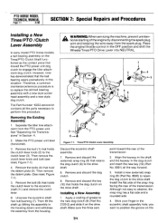
... holds the dog dutch on the drive shaft. Remove and discard the (external) snap ring (8) that moved the PTO power unit dog clutch to engage the tiller attachment dog clutch. you want to position the groove on the Tines/PTO Clutch Shaft functioned as the contact piece that retains the dog clutch... the drive shaft. 8. However, time has demonstrated that hold the detent plate (5). Then lift the shaft up (tilting the assembly in this procedure. Separate the tiller tine attachment from the housing. Then remove the clutch lever knob and bolt (see inset, Figure 7-1). 4.
... holds the dog dutch on the drive shaft. Remove and discard the (external) snap ring (8) that moved the PTO power unit dog clutch to engage the tiller attachment dog clutch. you want to position the groove on the Tines/PTO Clutch Shaft functioned as the contact piece that retains the dog clutch... the drive shaft. 8. However, time has demonstrated that hold the detent plate (5). Then lift the shaft up (tilting the assembly in this procedure. Separate the tiller tine attachment from the housing. Then remove the clutch lever knob and bolt (see inset, Figure 7-1). 4.
Technical Manual
Page 35
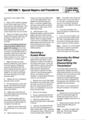
... right wheel is the same size. 2. Insert an old wheel shaft into the detent plate. Note: Soak the rim of grease to accept the tiller attachment sleeve. 10. SECTION 7: Special Repairs and Procedures PTO HORSE MODEL TECHNICAL MANUAL Page 7-2 4/90 dog clutch in this manual. Apply a thin... fingers only, gently thread the eccentric shaft hex nut/bushing (7) until it can still remove the wheel shaft by following the instructions in the ENGAGE position, slide the detent plate to the shaft, follow these instructions. Then try to use a pin that is rusted to the shaft, see...
... right wheel is the same size. 2. Insert an old wheel shaft into the detent plate. Note: Soak the rim of grease to accept the tiller attachment sleeve. 10. SECTION 7: Special Repairs and Procedures PTO HORSE MODEL TECHNICAL MANUAL Page 7-2 4/90 dog clutch in this manual. Apply a thin... fingers only, gently thread the eccentric shaft hex nut/bushing (7) until it can still remove the wheel shaft by following the instructions in the ENGAGE position, slide the detent plate to the shaft, follow these instructions. Then try to use a pin that is rusted to the shaft, see...


