
Owners Manual
Page 10
... Applicable signal 69 Controlling the projector by a computer 26 Operations Projection on the remote control 14 Loading batteries 15 Remote control operation 16 Installation and connections Floor-mounted projector placement 17 Lens shift function 20 Projector placement angle adjustment (Foot adjuster) .. 21 Ceiling-mounted projector placement 22...
... Applicable signal 69 Controlling the projector by a computer 26 Operations Projection on the remote control 14 Loading batteries 15 Remote control operation 16 Installation and connections Floor-mounted projector placement 17 Lens shift function 20 Projector placement angle adjustment (Foot adjuster) .. 21 Ceiling-mounted projector placement 22...
Owners Manual
Page 13
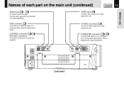
... COMPUTER (Y/PB/PR ) Left side Before use Names of a computer when using the presentation mode. USB connector 40 To connect to control the projector. CONTROL connector 26 71 (RS-232C connector) To connect a computer to a USB connector of each part on the main unit (continued) CONTENTS 13 AUDIO jack 23 - 25 (ø...
... COMPUTER (Y/PB/PR ) Left side Before use Names of a computer when using the presentation mode. USB connector 40 To connect to control the projector. CONTROL connector 26 71 (RS-232C connector) To connect a computer to a USB connector of each part on the main unit (continued) CONTENTS 13 AUDIO jack 23 - 25 (ø...
Owners Manual
Page 17
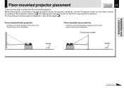
... set for the Floor-mounted front projection. Floor-mounted rear projection Viewing a picture projected through the back of the screen from a floor installation. Installation and connections Floor-mounted projector placement CONTENTS 17 There are two ways to the page 22 . For the ceiling-mounted projector placement, refer to place the floor...
... set for the Floor-mounted front projection. Floor-mounted rear projection Viewing a picture projected through the back of the screen from a floor installation. Installation and connections Floor-mounted projector placement CONTENTS 17 There are two ways to the page 22 . For the ceiling-mounted projector placement, refer to place the floor...
Owners Manual
Page 18
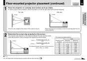
... Side view Screen Screen 90° KEYSTONE ON / STANDBY ON LAMP TEMP FAN ENTER EXIT AUTO SET VOL / ADJ 90° CONTENTS 18 Installation and connections MENU INPUT Point the lens straight at the center of the screen as shown below. The projection size depends on the distance between the lens...
... Side view Screen Screen 90° KEYSTONE ON / STANDBY ON LAMP TEMP FAN ENTER EXIT AUTO SET VOL / ADJ 90° CONTENTS 18 Installation and connections MENU INPUT Point the lens straight at the center of the screen as shown below. The projection size depends on the distance between the lens...
Owners Manual
Page 19
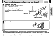
... 2 hours, depending on the projector. • Insert the other means. • If the screen and the projector are lit green. Installation and connections Floor-mounted projector placement (continued) 3 Connect the power cord. • Insert one end into a wall outlet. In such a case, leave the projector for several seconds and then the ON...
... 2 hours, depending on the projector. • Insert the other means. • If the screen and the projector are lit green. Installation and connections Floor-mounted projector placement (continued) 3 Connect the power cord. • Insert one end into a wall outlet. In such a case, leave the projector for several seconds and then the ON...
Owners Manual
Page 20
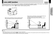
... and the turning direction of the lens shift dial becomes contrary from the case of the floor-mounted projector placement. Lens shift dial Installation and connections When the lens shift dial is turned counterclockwise fully, the projection position becomes the lowest. 50% 90° 50% When the lens shift dial is...
... and the turning direction of the lens shift dial becomes contrary from the case of the floor-mounted projector placement. Lens shift dial Installation and connections When the lens shift dial is turned counterclockwise fully, the projection position becomes the lowest. 50% 90° 50% When the lens shift dial is...
Owners Manual
Page 21
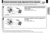
... this when the highest position by the foot adjusters, since the life duration of the lamp may be adjusted using the foot adjuster. Installation and connections Projector placement angle adjustment (Foot adjuster) CONTENTS 21 The tilt of the projector can be shortened. Refer to "Projection on your fingers. • Do not...
... this when the highest position by the foot adjusters, since the life duration of the lamp may be adjusted using the foot adjuster. Installation and connections Projector placement angle adjustment (Foot adjuster) CONTENTS 21 The tilt of the projector can be shortened. Refer to "Projection on your fingers. • Do not...
Owners Manual
Page 22
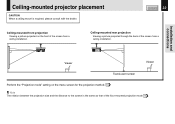
Installation and connections CONTROL USB AUDIO VIDEO S-VIDEO COMPUTER ( Y/PB/PR ) Viewer Viewer Translucent screen Perform the "Projection mode" setting on the front of the screen from a ceiling ...
Installation and connections CONTROL USB AUDIO VIDEO S-VIDEO COMPUTER ( Y/PB/PR ) Viewer Viewer Translucent screen Perform the "Projection mode" setting on the front of the screen from a ceiling ...
Owners Manual
Page 23
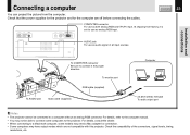
...connector. At shipping from the computer. For details, refer to the computer manual. • You may not be connected to a Macintosh computer, some computers to connect in the proper direction. CONTENTS 23 CONTROL USB AUDIO VIDEO S-VIDEO COMPUTER ( Y/PB/PR ) COMPUTER connector For... use as audio signal of the connectors, signal levels, timing, resolutions, etc. Check the compatibility of all input sources. Installation and connections To COMPUTER connector Be sure to the projector. To monitor port RGB cable (supplied) To AUDIO jack Audio cable (supplied) Computer ...
...connector. At shipping from the computer. For details, refer to the computer manual. • You may not be connected to a Macintosh computer, some computers to connect in the proper direction. CONTENTS 23 CONTROL USB AUDIO VIDEO S-VIDEO COMPUTER ( Y/PB/PR ) COMPUTER connector For... use as audio signal of the connectors, signal levels, timing, resolutions, etc. Check the compatibility of all input sources. Installation and connections To COMPUTER connector Be sure to the projector. To monitor port RGB cable (supplied) To AUDIO jack Audio cable (supplied) Computer ...
Owners Manual
Page 24
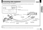
... equipment You can be used independently, but the audio input jack is used for the video equipment are off before connecting the cables. To S-video output S-video cable (not supplied) To AUDIO jack (Yellow) To VIDEO jack Video cable (supplied) Audio cable (supplied) Pin plug (red) ...
... equipment You can be used independently, but the audio input jack is used for the video equipment are off before connecting the cables. To S-video output S-video cable (not supplied) To AUDIO jack (Yellow) To VIDEO jack Video cable (supplied) Audio cable (supplied) Pin plug (red) ...
Owners Manual
Page 25
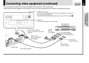
Change the setting on the menu screen when using as Y/PB/PR input. 44 Installation and connections AUDIO jack For use as both analog RGB and Y/PB/PR input. Check that the power supplies for the projector and for use as audio ... connector For use as analog RGB input. Video equipment (DVD player, etc.) To COMPUTER connector Be sure to connect in the proper direction. At shipping from video equipment with component video output jack. Connecting video equipment (continued) You can project the picture from factory, it is set for the video equipment are...
Change the setting on the menu screen when using as Y/PB/PR input. 44 Installation and connections AUDIO jack For use as both analog RGB and Y/PB/PR input. Check that the power supplies for the projector and for use as audio ... connector For use as analog RGB input. Video equipment (DVD player, etc.) To COMPUTER connector Be sure to connect in the proper direction. At shipping from video equipment with component video output jack. Connecting video equipment (continued) You can project the picture from factory, it is set for the video equipment are...
Owners Manual
Page 26
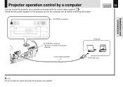
CONTROL USB AUDIO VIDEO S-VIDEO COMPUTER ( Y/PB/PR ) CONTROL connector CONTENTS 26 To CONTROL connector Be sure to connect in the proper direction. Control cable (supplied) Computer To RS-232C port Note Do not connect any cable other than the exclusive one supplied. Installation and connections Projector operation control by a computer You can control the projector by a computer connected with the control cable supplied. 71 Check that the power supplies for the projector and for the computer are off before connecting the cables.
CONTROL USB AUDIO VIDEO S-VIDEO COMPUTER ( Y/PB/PR ) CONTROL connector CONTENTS 26 To CONTROL connector Be sure to connect in the proper direction. Control cable (supplied) Computer To RS-232C port Note Do not connect any cable other than the exclusive one supplied. Installation and connections Projector operation control by a computer You can control the projector by a computer connected with the control cable supplied. 71 Check that the power supplies for the projector and for the computer are off before connecting the cables.
Owners Manual
Page 27
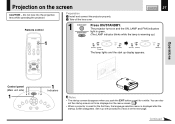
... the screen CONTENTS 27 CAUTION - Set it up display appears. Continued Do not look into the projection lens while operating the projector. Preparation 1 Install and connect the projector properly. 2 Take off the lens cover. ON/STANDBY (The LAMP indicator blinks while the lamp is displayed after the startup screen disappears.
... the screen CONTENTS 27 CAUTION - Set it up display appears. Continued Do not look into the projection lens while operating the projector. Preparation 1 Install and connect the projector properly. 2 Take off the lens cover. ON/STANDBY (The LAMP indicator blinks while the lamp is displayed after the startup screen disappears.
Owners Manual
Page 28
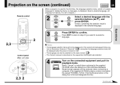
... RESIZE MENU VOL / ADJ 2 3 ENTER Press ENTER to confirm. Click the Browse button of the Add New Hardware Wizard screen appears on the computer when connecting a computer. (The supplied CD-ROM contains a driver information file named TOSHIBA_TLP.inf. Select a desired language. (At shipping from factory, it in playback mode. A menu confirming... language selection menu, which is to select a language for displaying menus or messages, is described on the supposition that English was selected. 4 Turn on the connected equipment and put it is displayed in the selected language.
... RESIZE MENU VOL / ADJ 2 3 ENTER Press ENTER to confirm. Click the Browse button of the Add New Hardware Wizard screen appears on the computer when connecting a computer. (The supplied CD-ROM contains a driver information file named TOSHIBA_TLP.inf. Select a desired language. (At shipping from factory, it in playback mode. A menu confirming... language selection menu, which is to select a language for displaying menus or messages, is described on the supposition that English was selected. 4 Turn on the connected equipment and put it is displayed in the selected language.
Owners Manual
Page 29
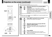
.... A picture of the selected input source appear on the screen. There are displayed here for two seconds. When a sound signal source is also connected, sound is pressed repeatedly can be selected. (You can be set from the menu screen. 44 5-b INPUT Press INPUT and hold for selection. ...source by pressing INPUT repeatedly. Note The types of input sources selected when the INPUT button is emitted from factory, "Analog RGB" connected to COMPUTER connector or "Video" connected to VIDEO Jack can select "Camera" when using the model with the selection buttons ( / ).
.... A picture of the selected input source appear on the screen. There are displayed here for two seconds. When a sound signal source is also connected, sound is pressed repeatedly can be selected. (You can be set from the menu screen. 44 5-b INPUT Press INPUT and hold for selection. ...source by pressing INPUT repeatedly. Note The types of input sources selected when the INPUT button is emitted from factory, "Analog RGB" connected to COMPUTER connector or "Video" connected to VIDEO Jack can select "Camera" when using the model with the selection buttons ( / ).
Owners Manual
Page 30
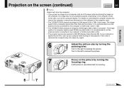
... up your computer is applied to enlarge the picture. It is recommended to set the external monitor connected to the computer to DDC2B (Display Data Channel 2B). It is recommended to set the external monitor connected to the computer to SVGA mode (800 x 600). • The projector can be projected properly, depending...
... up your computer is applied to enlarge the picture. It is recommended to set the external monitor connected to the computer to DDC2B (Display Data Channel 2B). It is recommended to set the external monitor connected to the computer to SVGA mode (800 x 600). • The projector can be projected properly, depending...
Owners Manual
Page 40
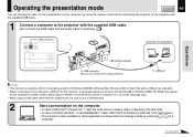
...174; or AcrobatReader®, make state that [Full Screen] is selected from [View] menu. • This function is installed. Also connect the RGB cable and the audio cable if necessary. 23 USB connector CONTROL USB AUDIO Computer for the first time, a message asking you to... software that can change a slide by using the remote control when connecting the projector to the computer with the supplied USB cable. 1 Connect a computer to the projector with a USB port as standard. • When connecting to the computer's USB port for presentation Operations USB cable (supplied)...
...174; or AcrobatReader®, make state that [Full Screen] is selected from [View] menu. • This function is installed. Also connect the RGB cable and the audio cable if necessary. 23 USB connector CONTROL USB AUDIO Computer for the first time, a message asking you to... software that can change a slide by using the remote control when connecting the projector to the computer with the supplied USB cable. 1 Connect a computer to the projector with a USB port as standard. • When connecting to the computer's USB port for presentation Operations USB cable (supplied)...

Owners Manual
Page 66
...projector. • Input is on . The image is heard. Correction Firmly plug in the power cord. Take off while using the projector. Connect the source correctly to the projector. Adjust the sound volume. Replace the lamp. No sound is blurred. The tint is faint. Make the ... are not correct. • The lamp life is ending. • The "Color", "Tint", "R-Level", "G-Level" or "B-Level" adjustments are not right. Connect the source correctly to the projector. Adjust the distance properly. By default, only the Analog RGB and Video input modes can be selected with the...
...projector. • Input is on . The image is heard. Correction Firmly plug in the power cord. Take off while using the projector. Connect the source correctly to the projector. Adjust the sound volume. Replace the lamp. No sound is blurred. The tint is faint. Make the ... are not correct. • The lamp life is ending. • The "Color", "Tint", "R-Level", "G-Level" or "B-Level" adjustments are not right. Connect the source correctly to the projector. Adjust the distance properly. By default, only the Analog RGB and Video input modes can be selected with the...
Owners Manual
Page 67
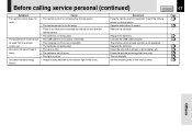
...Clean the lens with a blower or lens cleaner, etc. Turn on the menu screen. Set the shutter speed on the light. Remove the obstacle. Connect the USB cable properly. Focus the picture by fluorescent light in the room. Cause • The remote control is not facing the remote sensor. ...8226; There is an obstruction between the remote control and the remote sensor. • The batteries are exhausted. • The USB cable is not properly connected. • The computer or OS is not compatible. • The batteries are exhausted. • The lens is dirty. • The picture is out...
...Clean the lens with a blower or lens cleaner, etc. Turn on the menu screen. Set the shutter speed on the light. Remove the obstacle. Connect the USB cable properly. Focus the picture by fluorescent light in the room. Cause • The remote control is not facing the remote sensor. ...8226; There is an obstruction between the remote control and the remote sensor. • The batteries are exhausted. • The USB cable is not properly connected. • The computer or OS is not compatible. • The batteries are exhausted. • The lens is dirty. • The picture is out...

Owners Manual
Page 68
...) GND (Y) 8 GND (Blue) GND (PB) 9 N.C * 10 GND * 11 GND * 12 DDC data * 13 Horizontal sync signal * 14 Vertical sync signal * 15 DDC clock * * : Do not connect anything.
...) GND (Y) 8 GND (Blue) GND (PB) 9 N.C * 10 GND * 11 GND * 12 DDC data * 13 Horizontal sync signal * 14 Vertical sync signal * 15 DDC clock * * : Do not connect anything.


