User Guide 1
Page 28
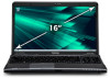
...other countries. Additional information may be implied for the personal and non-commercial use of a consumer to provide such video. 28 Trademarks Satellite and eco Utility are either registered trademarks or trademarks of Adobe Systems Incorporated in the United States and/or other countries. Adobe and ...from a video provider licensed to (i) encode video in compliance with this product in and recycling programs. For details, please visit www.laptops.toshiba.com/green. and any other use of such marks by the Bluetooth SIG, Inc. See www.mpegla.com. None of Synaptics, Inc.
...other countries. Additional information may be implied for the personal and non-commercial use of a consumer to provide such video. 28 Trademarks Satellite and eco Utility are either registered trademarks or trademarks of Adobe Systems Incorporated in the United States and/or other countries. Adobe and ...from a video provider licensed to (i) encode video in compliance with this product in and recycling programs. For details, please visit www.laptops.toshiba.com/green. and any other use of such marks by the Bluetooth SIG, Inc. See www.mpegla.com. None of Synaptics, Inc.

User Guide 1
Page 134
... injury. 134 Mobile Computing Disposing of used battery packs in serious injury. Failure to our shared environment. In addition, Toshiba's recycling initiatives include recycling programs, events and consumer promotions. Put insulating tape, such as an accessory or an equivalent ...or how to a heating apparatus (e.g., microwave oven). Use of the Rechargeable Battery Recycling Corporation. For details, please visit www.laptops.toshiba.com/green. Other battery packs have different voltage and terminal polarities. Under certain applicable laws and regulations, it into a fire,...
... injury. 134 Mobile Computing Disposing of used battery packs in serious injury. Failure to our shared environment. In addition, Toshiba's recycling initiatives include recycling programs, events and consumer promotions. Put insulating tape, such as an accessory or an equivalent ...or how to a heating apparatus (e.g., microwave oven). Use of the Rechargeable Battery Recycling Corporation. For details, please visit www.laptops.toshiba.com/green. Other battery packs have different voltage and terminal polarities. Under certain applicable laws and regulations, it into a fire,...

User Guide 1
Page 207
... at (800) 457-7777 Outside the United States at (949) 859-4273 Other Toshiba Internet Web sites toshiba.com laptops.toshiba.com accessories.toshiba.com www.toshiba.ca www.toshiba-Europe.com www.toshiba.co.jp/index.htm pcsupport.toshiba.com acclaim.toshiba.com laptopforums.toshiba.com Worldwide Toshiba corporate site Marketing and product information in the USA Accessories information in the...
... at (800) 457-7777 Outside the United States at (949) 859-4273 Other Toshiba Internet Web sites toshiba.com laptops.toshiba.com accessories.toshiba.com www.toshiba.ca www.toshiba-Europe.com www.toshiba.co.jp/index.htm pcsupport.toshiba.com acclaim.toshiba.com laptopforums.toshiba.com Worldwide Toshiba corporate site Marketing and product information in the USA Accessories information in the...
Maintenance Manual
Page 8
... Safety Precautions ...4-3 Before You Begin...4-5 Disassembly Procedures 4-6 Assembly Procedures ...4-6 Tools and Equipment ...4-7 Screw Tightening Torque 4-7 Colors of Screw Shanks 4-8 Symbols of Screws on the Laptop Body 4-8 Symbol examples ...4-8 4.2 Battery...4-9 Removing the Battery Pack 4-9 Installing the Battery Pack 4-10 4.3 HDD...4-11 Removing the HDD...4-11 Installing the HDD ...4-13 4.4 Memory... Card 4-21 Installing the WLAN Card 4-22 4.7 ODD...4-23 Removing the ODD Bay Module 4-23 Installing the ODD Bay Module 4-24 Satellite A660/ProA660 Series Maintenance Manual viii
... Safety Precautions ...4-3 Before You Begin...4-5 Disassembly Procedures 4-6 Assembly Procedures ...4-6 Tools and Equipment ...4-7 Screw Tightening Torque 4-7 Colors of Screw Shanks 4-8 Symbols of Screws on the Laptop Body 4-8 Symbol examples ...4-8 4.2 Battery...4-9 Removing the Battery Pack 4-9 Installing the Battery Pack 4-10 4.3 HDD...4-11 Removing the HDD...4-11 Installing the HDD ...4-13 4.4 Memory... Card 4-21 Installing the WLAN Card 4-22 4.7 ODD...4-23 Removing the ODD Bay Module 4-23 Installing the ODD Bay Module 4-24 Satellite A660/ProA660 Series Maintenance Manual viii
Maintenance Manual
Page 11
... from the ODD drive 4-25 Figure 4.18 Removing thirteen screws from the bottom of the laptop 4-26 Figure 4.19 Disconnecting the cables and removing the upper logic assembly screw ........ 4-27 Figure 4.20 Removing the logic upper assembly 4-27 Figure 4.21 Disassembling the Slot-load ODD 4-30 Satellite A660/ProA660 Series Maintenance Manual xi
... from the ODD drive 4-25 Figure 4.18 Removing thirteen screws from the bottom of the laptop 4-26 Figure 4.19 Disconnecting the cables and removing the upper logic assembly screw ........ 4-27 Figure 4.20 Removing the logic upper assembly 4-27 Figure 4.21 Disassembling the Slot-load ODD 4-30 Satellite A660/ProA660 Series Maintenance Manual xi

Maintenance Manual
Page 171
... Safety Precautions 4-3 Before You Begin 4-5 Disassembly Procedures 4-6 Assembly Procedures 4-6 Tools and Equipment 4-7 Screw Tightening Torque 4-7 Colors of Screw Shanks 4-8 Symbols of Screws on the Laptop Body 4-8 Symbol examples 4-8 4.2 Battery ...4-9 Removing the Battery Pack 4-9 Installing the Battery Pack 4-10 4.3 HDD ...4-11 Removing the HDD 4-11 Installing the HDD 4-13 4.4...Removing the WLAN Card 4-21 Installing the TV Tuner Card 4-21 Installing the WLAN Card 4-22 4.7 ODD Module (Tray-load 4-23 Satellite A660/ProA660 Series Maintenance Manual 4-ii
... Safety Precautions 4-3 Before You Begin 4-5 Disassembly Procedures 4-6 Assembly Procedures 4-6 Tools and Equipment 4-7 Screw Tightening Torque 4-7 Colors of Screw Shanks 4-8 Symbols of Screws on the Laptop Body 4-8 Symbol examples 4-8 4.2 Battery ...4-9 Removing the Battery Pack 4-9 Installing the Battery Pack 4-10 4.3 HDD ...4-11 Removing the HDD 4-11 Installing the HDD 4-13 4.4...Removing the WLAN Card 4-21 Installing the TV Tuner Card 4-21 Installing the WLAN Card 4-22 4.7 ODD Module (Tray-load 4-23 Satellite A660/ProA660 Series Maintenance Manual 4-ii
Maintenance Manual
Page 175
... ODD 4-24 Figure 4.17 Hooks on the inside of the Tray-load ODD bezel 4-25 Figure 4.18 Removing thirteen screws from the bottom of the laptop 4-26 Figure 4.19 Disconnecting the cables and removing the upper logic assembly screw ........ 4-27 Figure 4.20 Removing the logic upper assembly 4-27 Figure 4.21 Disassembling... Removing the speakers 4-37 Figure 4.28 Removing the speaker cushions 4-38 Figure 4.29 Removing the indicator board 4-39 Figure 4.30 Removing the USB board 4-40 Satellite A660/ProA660 Series Maintenance Manual 4-vi
... ODD 4-24 Figure 4.17 Hooks on the inside of the Tray-load ODD bezel 4-25 Figure 4.18 Removing thirteen screws from the bottom of the laptop 4-26 Figure 4.19 Disconnecting the cables and removing the upper logic assembly screw ........ 4-27 Figure 4.20 Removing the logic upper assembly 4-27 Figure 4.21 Disassembling... Removing the speakers 4-37 Figure 4.28 Removing the speaker cushions 4-38 Figure 4.29 Removing the indicator board 4-39 Figure 4.30 Removing the USB board 4-40 Satellite A660/ProA660 Series Maintenance Manual 4-vi

Maintenance Manual
Page 176
The FRUs shown in the top area of their physical locations. Next, according Satellite A660/ProA660 Series Maintenance Manual 4-vii To replace the FRUs, first identify the suspect FRU for the system failure. The chart below shows the FRUs in ... This chapter explains how to replace only one FRU. Some replacement procedures may not require you to remove all the surrounding FRUs to disassemble the laptop and replace Field Replaceable Units (FRUs).
The FRUs shown in the top area of their physical locations. Next, according Satellite A660/ProA660 Series Maintenance Manual 4-vii To replace the FRUs, first identify the suspect FRU for the system failure. The chart below shows the FRUs in ... This chapter explains how to replace only one FRU. Some replacement procedures may not require you to remove all the surrounding FRUs to disassemble the laptop and replace Field Replaceable Units (FRUs).
Maintenance Manual
Page 178
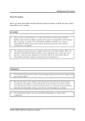
... the following safety precautions carefully. The components such as necklaces, bracelets and rings before starting work with the laptop. Safety Precautions 4 Replacement Procedures Before you are incompatible with damp or wet hands. 3. Be sure to ...Toshiba. If this is left charged, the risk of alkaline solutions, never heat or disassemble the battery packs. When you partially disassemble the laptop and turn the laptop off and remove the AC adapter from the electrical outlet. Do not disassemble individual components during first-level maintenance. Satellite A660...
... the following safety precautions carefully. The components such as necklaces, bracelets and rings before starting work with the laptop. Safety Precautions 4 Replacement Procedures Before you are incompatible with damp or wet hands. 3. Be sure to ...Toshiba. If this is left charged, the risk of alkaline solutions, never heat or disassemble the battery packs. When you partially disassemble the laptop and turn the laptop off and remove the AC adapter from the electrical outlet. Do not disassemble individual components during first-level maintenance. Satellite A660...
Maintenance Manual
Page 179
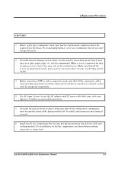
... to avoid the risk of electrical shock caused by accidental contact with your laptop or Toshiba-recommended equivalents. 5. Loose screws can cause short circuits, overheating, smoke or fire. 3. To avoid laptop failures, never use the AC adapter and AC power cable that all the...laptop and that come with the energized components. 4. To avoid burns, let the hot components cool down before starting inspection or repair task. For AC input, be sure to use components that is the same size as the original screw. Inside the PC are fastened securely. 6. Satellite A660...
... to avoid the risk of electrical shock caused by accidental contact with your laptop or Toshiba-recommended equivalents. 5. Loose screws can cause short circuits, overheating, smoke or fire. 3. To avoid laptop failures, never use the AC adapter and AC power cable that all the...laptop and that come with the energized components. 4. To avoid burns, let the hot components cool down before starting inspection or repair task. For AC input, be sure to use components that is the same size as the original screw. Inside the PC are fastened securely. 6. Satellite A660...
Maintenance Manual
Page 180
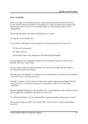
...to fasten the parts to the specified locations. 4 Replacement Procedures Before You Begin Before you doing your work. Disassemble the laptop only when an abnormality has occurred. The procedures for screw sizes. Perform only the required machine operations. Place the removed ...to disassemble the laptop, keep in mind the precautions and advice in this section. Remove the optional parts and accessories as well. See the appropriate explanations and figures for removing the batteries will be removed or replaced during disassembling. Satellite A660/ProA660 Series Maintenance...
...to fasten the parts to the specified locations. 4 Replacement Procedures Before You Begin Before you doing your work. Disassemble the laptop only when an abnormality has occurred. The procedures for screw sizes. Perform only the required machine operations. Place the removed ...to disassemble the laptop, keep in mind the precautions and advice in this section. Remove the optional parts and accessories as well. See the appropriate explanations and figures for removing the batteries will be removed or replaced during disassembling. Satellite A660/ProA660 Series Maintenance...

Maintenance Manual
Page 181
...or FRUs. Grasp and pull the cable gently to check that caused the problem. Assembly Procedures You have to reassemble the laptop after you have disassembled the laptop and fixed the component that the cable is flush with the sides of the connector. Before securing the FRUs or other ...of the pressure plate so that the FRU and laptop work normally. Using wrong screws can be installed or removed by pressing down the sides of the screws or does not ensure that all the cable and connectors are closed securely. Satellite A660/ProA660 Series Maintenance Manual 4-6 Secure the cable in...
...or FRUs. Grasp and pull the cable gently to check that caused the problem. Assembly Procedures You have to reassemble the laptop after you have disassembled the laptop and fixed the component that the cable is flush with the sides of the connector. Before securing the FRUs or other ...of the pressure plate so that the FRU and laptop work normally. Using wrong screws can be installed or removed by pressing down the sides of the screws or does not ensure that all the cable and connectors are closed securely. Satellite A660/ProA660 Series Maintenance Manual 4-6 Secure the cable in...
Maintenance Manual
Page 183
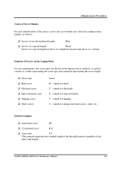
A symbol consists of the entire stud length.) Satellite A660/ProA660 Series Maintenance Manual 4-8 Screw type Bind screw Flat-head screw Super flat-head screw Tapping screw Other screws Letter B (stands for bind) F (stands for ... to their lengths, as follows: Screws of an odd-numbered length Blue Screws of a special length Black Screws of a special length are shown on the Laptop Body For easy maintenance, the screw types are those of a length having decimal places (i.e. 16mm). Symbols of Screws on the...
A symbol consists of the entire stud length.) Satellite A660/ProA660 Series Maintenance Manual 4-8 Screw type Bind screw Flat-head screw Super flat-head screw Tapping screw Other screws Letter B (stands for bind) F (stands for ... to their lengths, as follows: Screws of an odd-numbered length Blue Screws of a special length Black Screws of a special length are shown on the Laptop Body For easy maintenance, the screw types are those of a length having decimal places (i.e. 16mm). Symbols of Screws on the...

Maintenance Manual
Page 184
... latch and remove the battery pack from the laptop as required by local ordinances or regulations. Slide the battery safety lock to the following procedures and Figure 4.1. 4.2 Battery 4 Replacement Procedures Removing the Battery Pack Remove the battery pack according to the unlock position. 3. Satellite A660/ProA660 Series Maintenance Manual 4-9 Do not scratch or...
... latch and remove the battery pack from the laptop as required by local ordinances or regulations. Slide the battery safety lock to the following procedures and Figure 4.1. 4.2 Battery 4 Replacement Procedures Removing the Battery Pack Remove the battery pack according to the unlock position. 3. Satellite A660/ProA660 Series Maintenance Manual 4-9 Do not scratch or...

Maintenance Manual
Page 189
Satellite A660/ProA660 Series Maintenance Manual 4-14 Install the HDD pack into the laptop, do not press the center of the HDD pack. 4 Replacement Procedures M3x3*2 M3x3*2 Figure 4.6 Securing the HDD foil CAUTION: To prevent the HDD pack from being distorted when installing into the correct position in the laptop. Connect the HDD pack to the laptop. 4. Secure the HDD door by its sides. 3. Always hold the HDD pack by tightening one M2.5x8 screw.
Satellite A660/ProA660 Series Maintenance Manual 4-14 Install the HDD pack into the laptop, do not press the center of the HDD pack. 4 Replacement Procedures M3x3*2 M3x3*2 Figure 4.6 Securing the HDD foil CAUTION: To prevent the HDD pack from being distorted when installing into the correct position in the laptop. Connect the HDD pack to the laptop. 4. Secure the HDD door by its sides. 3. Always hold the HDD pack by tightening one M2.5x8 screw.

Maintenance Manual
Page 190
CAUTION: Remove the optional memory after checking that the laptop is violated, the laptop or memory can cause memory access problems. M2.5x5*1 Figure 4.7 Removing the RAM door Satellite A660/ProA660 Series Maintenance Manual 4-15 If this is turned off the laptop. Turn the laptop upside down. 2. Remove the RAM door. CAUTION: Do not touch the connectors...
CAUTION: Remove the optional memory after checking that the laptop is violated, the laptop or memory can cause memory access problems. M2.5x5*1 Figure 4.7 Removing the RAM door Satellite A660/ProA660 Series Maintenance Manual 4-15 If this is turned off the laptop. Turn the laptop upside down. 2. Remove the RAM door. CAUTION: Do not touch the connectors...

Maintenance Manual
Page 191
...after turning off . Repeat steps 1 and 2 to remove the lower memory module. Secure the RAM door with both memory lock latches. 3. Satellite A660/ProA660 Series Maintenance Manual 4-16 Please follow the procedure as shown in the Hardware Setup or TESTUP program to avoid touching the connectors. 6. ...Pull the upper memory module up . If this is turned off the laptop. 4 Replacement Procedures 4. After the laptop is turned on the memory module so that the laptop is violated, the laptop or memory can be damaged. 1.
...after turning off . Repeat steps 1 and 2 to remove the lower memory module. Secure the RAM door with both memory lock latches. 3. Satellite A660/ProA660 Series Maintenance Manual 4-16 Please follow the procedure as shown in the Hardware Setup or TESTUP program to avoid touching the connectors. 6. ...Pull the upper memory module up . If this is turned off the laptop. 4 Replacement Procedures 4. After the laptop is turned on the memory module so that the laptop is violated, the laptop or memory can be damaged. 1.
Maintenance Manual
Page 192
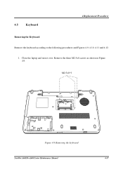
Remove the three M2.5x8 screws as shown in Figure 4.9. 4.5 Keyboard 4 Replacement Procedures Removing the Keyboard Remove the keyboard according to the following procedures and Figures 4.9, 4.10, 4.11 and 4.12. 1. M2.5x8*3 Figure 4.9 Removing the keyboard Satellite A660/ProA660 Series Maintenance Manual 4-17 Close the laptop and turn it over.
Remove the three M2.5x8 screws as shown in Figure 4.9. 4.5 Keyboard 4 Replacement Procedures Removing the Keyboard Remove the keyboard according to the following procedures and Figures 4.9, 4.10, 4.11 and 4.12. 1. M2.5x8*3 Figure 4.9 Removing the keyboard Satellite A660/ProA660 Series Maintenance Manual 4-17 Close the laptop and turn it over.

Maintenance Manual
Page 194
... cables and removing the keyboard Installing the Keyboard Install the Keyboard according to click into place, making sure the keyboard is secure at all points. 3. Satellite A660/ProA660 Series Maintenance Manual 4-19 Connect the two cables on the back of the keyboard to the motherboard. 2. Place the keyboard in Figure 4.12. ...on the back of the keyboard from the motherboard as shown in the correct position and press firmly downward to the following procedures. 1. Close the laptop and flip it over. 4. Remove the keyboard. Secure the keyboard with three M2.5x8 screws.
... cables and removing the keyboard Installing the Keyboard Install the Keyboard according to click into place, making sure the keyboard is secure at all points. 3. Satellite A660/ProA660 Series Maintenance Manual 4-19 Connect the two cables on the back of the keyboard to the motherboard. 2. Place the keyboard in Figure 4.12. ...on the back of the keyboard from the motherboard as shown in the correct position and press firmly downward to the following procedures. 1. Close the laptop and flip it over. 4. Remove the keyboard. Secure the keyboard with three M2.5x8 screws.
Maintenance Manual
Page 198
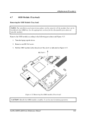
... the appropriate sections for all the modules that can become hot during operation. Pull the ODD module in the direction of specific modules. Turn the laptop upside down. 2. 4 Replacement Procedures 4.7 ODD Module (Tray-load) Removing the ODD Module (Tray-load) NOTE: The installation and removal procedures are the same for... according to the following procedures and Figure 4.15. 1. M2.5x8*1 Figure 4.15 Removing the ODD module (Tray-load) CAUTION: Handle the ODD module carefully. Satellite A660/ProA660 Series Maintenance Manual 4-23 It can be installed in the ODD bay.
... the appropriate sections for all the modules that can become hot during operation. Pull the ODD module in the direction of specific modules. Turn the laptop upside down. 2. 4 Replacement Procedures 4.7 ODD Module (Tray-load) Removing the ODD Module (Tray-load) NOTE: The installation and removal procedures are the same for... according to the following procedures and Figure 4.15. 1. M2.5x8*1 Figure 4.15 Removing the ODD module (Tray-load) CAUTION: Handle the ODD module carefully. Satellite A660/ProA660 Series Maintenance Manual 4-23 It can be installed in the ODD bay.


