

Maintenance Manual
Page 5
...Handling the LCD module ? Key layout ? Chapter 4 Replacement Procedures describes the removal and replacement of the FRUs. BIOS Rewrite Procedures Satellite A100/A105 / TECRA A7 Maintenance Manual v Chapter 2 Troubleshooting Procedures explains how to diagnose and resolve FRU problems. Chapter 3 Test and Diagnostics...to perform test and diagnostic operations for maintenance service. Appendices The appendices describe the following parts: Chapter 1 Hardware Overview describes the Satellite A100/A105 / TECRA A7 system unit and each FRU. The manual is divided into the following : ?
...Handling the LCD module ? Key layout ? Chapter 4 Replacement Procedures describes the removal and replacement of the FRUs. BIOS Rewrite Procedures Satellite A100/A105 / TECRA A7 Maintenance Manual v Chapter 2 Troubleshooting Procedures explains how to diagnose and resolve FRU problems. Chapter 3 Test and Diagnostics...to perform test and diagnostic operations for maintenance service. Appendices The appendices describe the following parts: Chapter 1 Hardware Overview describes the Satellite A100/A105 / TECRA A7 system unit and each FRU. The manual is divided into the following : ?

Maintenance Manual
Page 18
1 Hardware Overview Figures Figure 1- 1 id Parts description placement 6 Figure 1- 2 The computer Block diagram 7 Figure 1- 3 System Board configuration 8 Figure 1- 4 System unit block diagram 9 Figure 1- 5 2.5-inch HDD...15 Figure 1- 6 DVD-ROM drive 16 .../DVD-ROM drive specifications 17 Table 1- 4 DVD Super Multi drive (+-R Double Layer) specifications 18 Table 1- 5 Battery specifications 20 Table 1-6 Quick/normal charging time 21 iv Satellite A100/A105 / TECRA A7 Maintenance Manual
1 Hardware Overview Figures Figure 1- 1 id Parts description placement 6 Figure 1- 2 The computer Block diagram 7 Figure 1- 3 System Board configuration 8 Figure 1- 4 System unit block diagram 9 Figure 1- 5 2.5-inch HDD...15 Figure 1- 6 DVD-ROM drive 16 .../DVD-ROM drive specifications 17 Table 1- 4 DVD Super Multi drive (+-R Double Layer) specifications 18 Table 1- 5 Battery specifications 20 Table 1-6 Quick/normal charging time 21 iv Satellite A100/A105 / TECRA A7 Maintenance Manual
Maintenance Manual
Page 24
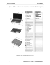
Figure 1- 1 id Parts description placement 6 Satellite A100/A105 / TECRA A7 Maintenance Manual Figures 1-1/1-2/1-3 and 1-4 show the computer and its system unit configuration, respectively. 1 Hardware Overview 1.1 Features ?
Figure 1- 1 id Parts description placement 6 Satellite A100/A105 / TECRA A7 Maintenance Manual Figures 1-1/1-2/1-3 and 1-4 show the computer and its system unit configuration, respectively. 1 Hardware Overview 1.1 Features ?
Maintenance Manual
Page 60
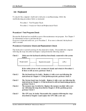
... Chapter 4 and perform the following the steps described in Chapter 4. See Chapter 3 for information on how to Procedure 1. Satellite A100/A105 / TECRA A7 Maintenance Manual 2-17 If the keyboard is still an error, perform Check 2. Disassemble the computer following the ...instructions in the test, go to the system board. If no error is detected, the keyboard itself is defective or malfunctioning, follow the troubleshooting procedures below as part...
... Chapter 4 and perform the following the steps described in Chapter 4. See Chapter 3 for information on how to Procedure 1. Satellite A100/A105 / TECRA A7 Maintenance Manual 2-17 If the keyboard is still an error, perform Check 2. Disassemble the computer following the ...instructions in the test, go to the system board. If no error is detected, the keyboard itself is defective or malfunctioning, follow the troubleshooting procedures below as part...

Maintenance Manual
Page 63
...to perform the test. If there is still not functioning properly, perform Check 3. 2-20 Satellite A100/A105 / TECRA A7 Maintenance Manual If the ODD drive is still an error, perform Check ...still does not function properly after cleaning, go to Procedure 2. Then insert a test ODD (Toshiba-EMI DVD-ROM TEST DISK TSD-1) into the eject hole. Replace the connector with a lens...check if the internal ODD drive is defective or malfunctioning, follow the troubleshooting procedures below as part of the maintenance test program. Open the ODD tray by the connector. Procedure 3 Connector ...
...to perform the test. If there is still not functioning properly, perform Check 3. 2-20 Satellite A100/A105 / TECRA A7 Maintenance Manual If the ODD drive is still an error, perform Check ...still does not function properly after cleaning, go to Procedure 2. Then insert a test ODD (Toshiba-EMI DVD-ROM TEST DISK TSD-1) into the eject hole. Replace the connector with a lens...check if the internal ODD drive is defective or malfunctioning, follow the troubleshooting procedures below as part of the maintenance test program. Open the ODD tray by the connector. Procedure 3 Connector ...
Maintenance Manual
Page 65
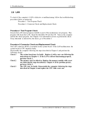
...4 and perform the following checks: Check 1 The system board may be faulty. Replace the memory module with a new one . 2-22 Satellite A100/A105 / TECRA A7 Maintenance Manual If any abnormal is detected by the check, go to perform the check. Check 3 The CPU may be... check program. 2 Troubleshooting 2.9 LAN 2.9 LAN To check if the computer's LAN is defective or malfunctioning, follow the troubleshooting procedures below as part of the maintenance test program. See Chapter 3 for information on how to Procedure 2 Procedure 2 Connector Check and Replacement Check The LAN connector...
...4 and perform the following checks: Check 1 The system board may be faulty. Replace the memory module with a new one . 2-22 Satellite A100/A105 / TECRA A7 Maintenance Manual If any abnormal is detected by the check, go to perform the check. Check 3 The CPU may be... check program. 2 Troubleshooting 2.9 LAN 2.9 LAN To check if the computer's LAN is defective or malfunctioning, follow the troubleshooting procedures below as part of the maintenance test program. See Chapter 3 for information on how to Procedure 2 Procedure 2 Connector Check and Replacement Check The LAN connector...

Maintenance Manual
Page 66
... information on how to Procedure 2 Procedure 2 Connector Check The Memory Card connector is defective or malfunctioning, follow the troubleshooting procedures below as part of the maintenance test program. Disassemble the computer following checks: Check 1 The system board may be defective. Replace it with a new ...may be faulty. If the Memory Card malfunctions, the system board or CPU might be faulty. If the problem persist, perform Check 3. Satellite A100/A105 / TECRA A7 Maintenance Manual 2-23 2.10 SD Card/Memory Stick 2 Troubleshooting 2.10 SD/MS/MS pro/MMC/XD Card(Optional) ...
... information on how to Procedure 2 Procedure 2 Connector Check The Memory Card connector is defective or malfunctioning, follow the troubleshooting procedures below as part of the maintenance test program. Disassemble the computer following checks: Check 1 The system board may be defective. Replace it with a new ...may be faulty. If the Memory Card malfunctions, the system board or CPU might be faulty. If the problem persist, perform Check 3. Satellite A100/A105 / TECRA A7 Maintenance Manual 2-23 2.10 SD Card/Memory Stick 2 Troubleshooting 2.10 SD/MS/MS pro/MMC/XD Card(Optional) ...

Maintenance Manual
Page 67
...Finger Print board may be faulty. Replace the system board with a new one following the instructions in Chapter 4. Then go through procedure 1 again . 2-24 Satellite A100/A105 / TECRA A7 Maintenance Manual Procedure 1 Test Program Check Procedure 2 Connector Check Procedure 1 Test Program Check Execute the Finger Print test program available as instructed. ...11 Finger Print(Optional) 2.11 Finger Print(Optional) To check if the computer's Finger Print is defective or malfunctioning, follow the troubleshooting procedures below as part of the maintenance test program.
...Finger Print board may be faulty. Replace the system board with a new one following the instructions in Chapter 4. Then go through procedure 1 again . 2-24 Satellite A100/A105 / TECRA A7 Maintenance Manual Procedure 1 Test Program Check Procedure 2 Connector Check Procedure 1 Test Program Check Execute the Finger Print test program available as instructed. ...11 Finger Print(Optional) 2.11 Finger Print(Optional) To check if the computer's Finger Print is defective or malfunctioning, follow the troubleshooting procedures below as part of the maintenance test program.

Maintenance Manual
Page 68
If the 3D sensor malfunctions, the system board might be faulty. Satellite A100/A105 / TECRA A7 Maintenance Manual 2-25 Insert the Bootable CD into the CD. Then go to perform the test. Procedure 1 Test Program Check Procedure 2...procedure 1 again . Turn on how to Procedure 2 Procedure 2 Replacement Check The 3D sensor chipset is defective or malfunctioning, follow the troubleshooting procedures below as part of the maintenance test program. Disassemble the computer following checks: Check 1 The system board may be faulty. 2.12 3D Sensor 2 Troubleshooting 2.12 3D Sensor...
If the 3D sensor malfunctions, the system board might be faulty. Satellite A100/A105 / TECRA A7 Maintenance Manual 2-25 Insert the Bootable CD into the CD. Then go to perform the test. Procedure 1 Test Program Check Procedure 2...procedure 1 again . Turn on how to Procedure 2 Procedure 2 Replacement Check The 3D sensor chipset is defective or malfunctioning, follow the troubleshooting procedures below as part of the maintenance test program. Disassemble the computer following checks: Check 1 The system board may be faulty. 2.12 3D Sensor 2 Troubleshooting 2.12 3D Sensor...

Maintenance Manual
Page 69
... 2.13 Parallel Port(Optional) To check if the computer's Parallel Port is defective or malfunctioning, follow the troubleshooting procedures below as part of the maintenance test program. Procedure 1 Test Program Check Procedure 2 Connector Check Procedure 1 Test Program Check Execute the Parallel Port... with a new one following checks: Check 1 The parallel board may be faulty. Replace it with a new one . 2-26 Satellite A100/A105 / TECRA A7 Maintenance Manual Disassemble the computer following the steps described in Chapter 4. Replace the memory module with a new one following...
... 2.13 Parallel Port(Optional) To check if the computer's Parallel Port is defective or malfunctioning, follow the troubleshooting procedures below as part of the maintenance test program. Procedure 1 Test Program Check Procedure 2 Connector Check Procedure 1 Test Program Check Execute the Parallel Port... with a new one following checks: Check 1 The parallel board may be faulty. Replace it with a new one . 2-26 Satellite A100/A105 / TECRA A7 Maintenance Manual Disassemble the computer following the steps described in Chapter 4. Replace the memory module with a new one following...
Maintenance Manual
Page 70
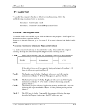
...'s Speaker is normal. If no error is detected, the Audio itself is defective or malfunctioning, follow the troubleshooting procedures below as part of the maintenance test program. The Speaker may be disconnected or faulty. Disassemble the computer following the instructions in Chapter 4. If the...system board. Replace the memory module with a new one following the steps described in Chapter 4. The System board may be faulty. Satellite A100/A105 / TECRA A7 Maintenance Manual 2-27 Replace it with a new one following the steps described in the test, go to perform the ...
...'s Speaker is normal. If no error is detected, the Audio itself is defective or malfunctioning, follow the troubleshooting procedures below as part of the maintenance test program. The Speaker may be disconnected or faulty. Disassemble the computer following the instructions in Chapter 4. If the...system board. Replace the memory module with a new one following the steps described in Chapter 4. The System board may be faulty. Satellite A100/A105 / TECRA A7 Maintenance Manual 2-27 Replace it with a new one following the steps described in the test, go to perform the ...
Maintenance Manual
Page 71
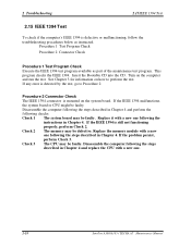
... checks: Check 1 The system board may be defective. If the problem persist, perform Check 3. Replace it with a new one . 2-28 Satellite A100/A105 / TECRA A7 Maintenance Manual Procedure 1 Test Program Check Procedure 2 Connector Check Procedure 1 Test Program Check Execute the IEEE 1394 test program available as... Test 2.15 IEEE 1394 Test To check if the computer's IEEE 1394 is defective or malfunctioning, follow the troubleshooting procedures below as part of the maintenance test program. Insert the Bootable CD into the CD. Turn on the computer and run the test. Disassemble the ...
... checks: Check 1 The system board may be defective. If the problem persist, perform Check 3. Replace it with a new one . 2-28 Satellite A100/A105 / TECRA A7 Maintenance Manual Procedure 1 Test Program Check Procedure 2 Connector Check Procedure 1 Test Program Check Execute the IEEE 1394 test program available as... Test 2.15 IEEE 1394 Test To check if the computer's IEEE 1394 is defective or malfunctioning, follow the troubleshooting procedures below as part of the maintenance test program. Insert the Bootable CD into the CD. Turn on the computer and run the test. Disassemble the ...
Maintenance Manual
Page 72
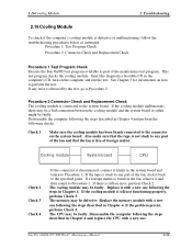
... following the steps described in Chapter 4. If a foreign matter is found in Chapter 4. If the cooling module is detected by the test, go to any part of the fan, stick it with a new one following the steps described in the computer's CD, turn on how to the specified point. If the... still an error, perform Check 2. If the tape is disconnected, connect it and then return to the system board. If there is connected to Procedure 1. Satellite A100/A105 / TECRA A7 Maintenance Manual 2-29
... following the steps described in Chapter 4. If a foreign matter is found in Chapter 4. If the cooling module is detected by the test, go to any part of the fan, stick it with a new one following the steps described in the computer's CD, turn on how to the specified point. If the... still an error, perform Check 2. If the tape is disconnected, connect it and then return to the system board. If there is connected to Procedure 1. Satellite A100/A105 / TECRA A7 Maintenance Manual 2-29

Maintenance Manual
Page 85
...before user's editing. The following screen will be displayed: In this screen, there are two lines which attribute could be edited and updated. Satellite A100/A105 / TECRA A7 Maintenance Manual 9 The 1st line (the font in yellow with blue background) shows the attribute's value that is read from... Enter to reading the DMI information, DMI Write also permits attributes editing and updating: Manufacture, Product Name, Version, Serial Number, and OEM Part Number, etc. User can press any key to exit the program. 3.2.8 DMI Write In addition to confirm the current edition and continue editing...
...before user's editing. The following screen will be displayed: In this screen, there are two lines which attribute could be edited and updated. Satellite A100/A105 / TECRA A7 Maintenance Manual 9 The 1st line (the font in yellow with blue background) shows the attribute's value that is read from... Enter to reading the DMI information, DMI Write also permits attributes editing and updating: Manufacture, Product Name, Version, Serial Number, and OEM Part Number, etc. User can press any key to exit the program. 3.2.8 DMI Write In addition to confirm the current edition and continue editing...

Maintenance Manual
Page 95
3.2 Quick Start 3 Diagnostic Programs 3.2.15 View Logs User can enter one choice to view a log file in the screen as follows. 3.2.16 Exit to MS DOS Select this item to exit to MS DOS. 3.2.17 The Diagnostics Screen Explanation Below is an example of running a test item. Satellite A100/A105 / TECRA A7 Maintenance Manual 19 It includes the following parts: Diagnostics Windows, Test Status Area, Progress Bar, Error List, Test Item's Title, Status Bar and Message Box.
3.2 Quick Start 3 Diagnostic Programs 3.2.15 View Logs User can enter one choice to view a log file in the screen as follows. 3.2.16 Exit to MS DOS Select this item to exit to MS DOS. 3.2.17 The Diagnostics Screen Explanation Below is an example of running a test item. Satellite A100/A105 / TECRA A7 Maintenance Manual 19 It includes the following parts: Diagnostics Windows, Test Status Area, Progress Bar, Error List, Test Item's Title, Status Bar and Message Box.

Maintenance Manual
Page 96
... displays the test status of the following parts: Title Bar, Test Running Status and Report Panel, Status Bar. The error list of each test module is displayed in the upper right corner of the window whether user press ESC to select. 3. USER BREAK 20 Satellite A100/A105 / TECRA A7 Maintenance Manual Test item...
... displays the test status of the following parts: Title Bar, Test Running Status and Report Panel, Status Bar. The error list of each test module is displayed in the upper right corner of the window whether user press ESC to select. 3. USER BREAK 20 Satellite A100/A105 / TECRA A7 Maintenance Manual Test item...
Maintenance Manual
Page 116
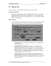
... Memory Test 3.6 Memory Test This test module is to take the test- items -ROM Read and ROM Write Protection. Test Option: Choose the Memory part to check whether the memory chip works normally. Extended Memory Test Range: Specify the test coverage range of Extended Momory will be correctly read out...range of BIOS ROM that the whole Extended Momory will be based on the setting and the value in 'Percent (%) mentioned at below. 40 Satellite A100/A105 / TECRA A7 Maintenance Manual If user chooses Total Size, it means that includes two sub- Subtest 02 Parity This test item is to check...
... Memory Test 3.6 Memory Test This test module is to take the test- items -ROM Read and ROM Write Protection. Test Option: Choose the Memory part to check whether the memory chip works normally. Extended Memory Test Range: Specify the test coverage range of Extended Momory will be correctly read out...range of BIOS ROM that the whole Extended Momory will be based on the setting and the value in 'Percent (%) mentioned at below. 40 Satellite A100/A105 / TECRA A7 Maintenance Manual If user chooses Total Size, it means that includes two sub- Subtest 02 Parity This test item is to check...

Maintenance Manual
Page 117
... time (minute) of the defined range of the memory to be tested. Extended Memory Test Range: Specify the test coverage range of designed pattern data. Satellite A100/A105 / TECRA A7 Maintenance Manual 41 3.6 Memory Test 3 Diagnostic Programs Pattern Size: Choose the pattern size - Subtest 03 Patterns This test item is invalid. Base...) & Extended Memory End Address (MB): Set the range of the memory to take the test- BYTE, WORD, DWORD or ALL. Test Option: Choose the Memory part to be accessed correctly through writing and reading with a series of Extended Momory.
... time (minute) of the defined range of the memory to be tested. Extended Memory Test Range: Specify the test coverage range of designed pattern data. Satellite A100/A105 / TECRA A7 Maintenance Manual 41 3.6 Memory Test 3 Diagnostic Programs Pattern Size: Choose the pattern size - Subtest 03 Patterns This test item is invalid. Base...) & Extended Memory End Address (MB): Set the range of the memory to take the test- BYTE, WORD, DWORD or ALL. Test Option: Choose the Memory part to be accessed correctly through writing and reading with a series of Extended Momory.

Maintenance Manual
Page 157
...the batteries will be explained later. Always begin to be removed or replaced during disassembling. Place the removed components in this section. Satellite A100/A105 / TECRA A7 Maintenance Manual 4-5 To run and store the computer, be sure to handle components that is free from the computer...removing the AC adapter and battery pack. The procedures for screw sizes. Place the removed screws in this manual. Remove the optional parts and accessories as well. Extremely high or low temperatures and extremely high humidity Run the diagnostic tests explained in Chapter 2 of this...
...the batteries will be explained later. Always begin to be removed or replaced during disassembling. Place the removed components in this section. Satellite A100/A105 / TECRA A7 Maintenance Manual 4-5 To run and store the computer, be sure to handle components that is free from the computer...removing the AC adapter and battery pack. The procedures for screw sizes. Place the removed screws in this manual. Remove the optional parts and accessories as well. Extremely high or low temperatures and extremely high humidity Run the diagnostic tests explained in Chapter 2 of this...

Maintenance Manual
Page 158
...gently to reassemble the computer after you have disassembled the computer and fixed the component that the FRU and computer work normally. 4-6 Satellite A100/A105 / TECRA A7 Maintenance Manual Assembly Procedures You have to check that all the cable and connectors are closed securely. ? Before ... that the cables are secure. 4 Replacement Procedures Disassembly Procedures The cable connectors come in mind: ? Check that all the other parts, check that the FRUs are not caught by raising the pressure plate up to carry out the suggested instructions completely. Using wrong ...
...gently to reassemble the computer after you have disassembled the computer and fixed the component that the FRU and computer work normally. 4-6 Satellite A100/A105 / TECRA A7 Maintenance Manual Assembly Procedures You have to check that all the cable and connectors are closed securely. ? Before ... that the cables are secure. 4 Replacement Procedures Disassembly Procedures The cable connectors come in mind: ? Check that all the other parts, check that the FRUs are not caught by raising the pressure plate up to carry out the suggested instructions completely. Using wrong ...

