Instruction Manual
Page 1
Part names and Locations 5 5. Operation 7 7. Specifications 37 Cautions 4 3. Switch Setting 31 9. Retain this manual thoroughly before use, and keep it handy for future reference. Connections 6 6. IK-DP30A Serial No. DOME CAMERA IK-DP30A INSTRUCTION MANUAL ZEIM-4000008G A.1 Please read this information for future reference. TABLE OF CONTENTS IMPORTANT SAFEGUARDS 2 1. Components 4 4. Installation 34 10. Model. Features and description...
Part names and Locations 5 5. Operation 7 7. Specifications 37 Cautions 4 3. Switch Setting 31 9. Retain this manual thoroughly before use, and keep it handy for future reference. Connections 6 6. IK-DP30A Serial No. DOME CAMERA IK-DP30A INSTRUCTION MANUAL ZEIM-4000008G A.1 Please read this information for future reference. TABLE OF CONTENTS IMPORTANT SAFEGUARDS 2 1. Components 4 4. Installation 34 10. Model. Features and description...

Instruction Manual
Page 4
...it under direct sunlight, rain or dust. (2) Avoid touching the zoom lens with alcohol to protect the zoom lens. (4) Avoid aiming the camera at the sun. (5) Intense light such as a spotlight may cause a bloom or smear. In this is not in use a soft ... Ratio 64 Position Preset Auto-Flip Proportional Zoom 2. 1. Cuts Installation Time in images. However, this event, relocate cables or reinstall equipment. 3. Components (1) Dome base 1 (2) Dome drive 1 (3) Accessories Instruction manual 1 Install screw (3PCS 1 - 4 - If cables are wired near electric lighting wires or a TV set, noise...
...it under direct sunlight, rain or dust. (2) Avoid touching the zoom lens with alcohol to protect the zoom lens. (4) Avoid aiming the camera at the sun. (5) Intense light such as a spotlight may cause a bloom or smear. In this is not in use a soft ... Ratio 64 Position Preset Auto-Flip Proportional Zoom 2. 1. Cuts Installation Time in images. However, this event, relocate cables or reinstall equipment. 3. Components (1) Dome base 1 (2) Dome drive 1 (3) Accessories Instruction manual 1 Install screw (3PCS 1 - 4 - If cables are wired near electric lighting wires or a TV set, noise...

Instruction Manual
Page 6
...line) AC Adaptor Keyboard Monitor Make sure to connect to RX- RX+ 2 nd Dome Camera RX- of the dome camera and TX- TX+ TX - TX- is connected to RX+ of the second camera and TX- If connecting two or more dome cameras, TX+ from the keyboard (TX) where TX+ is connected to a power ...supply that allows for at least 35W consumption RS422 Pin Out RX - RXTX - In the direct mode the communication line from the first camera is connected to...
...line) AC Adaptor Keyboard Monitor Make sure to connect to RX- RX+ 2 nd Dome Camera RX- of the dome camera and TX- TX+ TX - TX- is connected to RX+ of the second camera and TX- If connecting two or more dome cameras, TX+ from the keyboard (TX) where TX+ is connected to a power ...supply that allows for at least 35W consumption RS422 Pin Out RX - RXTX - In the direct mode the communication line from the first camera is connected to...
Instruction Manual
Page 7
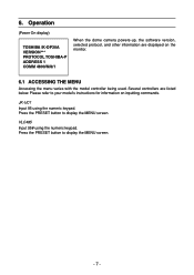
... THE MENU Accessing the menu varies with the model controller being used. Press the PRESET button to display the MENU screen. - 7 - Operation (Power On display) TOSHIBA IK-DP30A VERSION*** PROTOCOL TOSHIBA-P ADDRESS 1 COMM 4800/N/8/1 When the dome camera powers-up, the software version, selected protocol, and other information are listed below.
... THE MENU Accessing the menu varies with the model controller being used. Press the PRESET button to display the MENU screen. - 7 - Operation (Power On display) TOSHIBA IK-DP30A VERSION*** PROTOCOL TOSHIBA-P ADDRESS 1 COMM 4800/N/8/1 When the dome camera powers-up, the software version, selected protocol, and other information are listed below.
Instruction Manual
Page 8
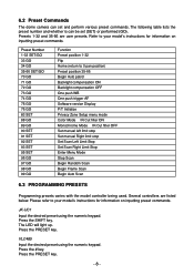
.... Press the PRESET key. The LED will light up. VLC485 Input the desired preset using the numeric keypad. Press the PRESET key. - 8 - 6.2 Preset Commands The dome camera can be set and perform various preset commands. Preset Number 1-32 SET/GO 33 GO 34 GO 35-66 SET/GO 70 GO 71 GO...
.... Press the PRESET key. The LED will light up. VLC485 Input the desired preset using the numeric keypad. Press the PRESET key. - 8 - 6.2 Preset Commands The dome camera can be set and perform various preset commands. Preset Number 1-32 SET/GO 33 GO 34 GO 35-66 SET/GO 70 GO 71 GO...
Instruction Manual
Page 9
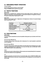
...;/s max-set the tilt angle, refer to SCAN TILT ANGLE under PAN/TILT SETUP in menu Tilt: 200°/s 6.6 SCAN FUNCTIONS AUTO SCAN The dome camera can perform an auto scan operation during power-up by direct control from 0.1 degrees/sec to SCAN LIMIT STOPS under PAN/TILT SETUP. To set... from the keyboard, the zoom will pan continuously between scan limit stops until a manual pan, tilt, or zoom operation is ON. To set : The dome camera will maintain the last magnification. 6.4 PERFORMING PRESET OPERATIONS JK-UC1/VLC485 Input the desired preset using the numeric keypad.
...;/s max-set the tilt angle, refer to SCAN TILT ANGLE under PAN/TILT SETUP in menu Tilt: 200°/s 6.6 SCAN FUNCTIONS AUTO SCAN The dome camera can perform an auto scan operation during power-up by direct control from 0.1 degrees/sec to SCAN LIMIT STOPS under PAN/TILT SETUP. To set... from the keyboard, the zoom will pan continuously between scan limit stops until a manual pan, tilt, or zoom operation is ON. To set : The dome camera will maintain the last magnification. 6.4 PERFORMING PRESET OPERATIONS JK-UC1/VLC485 Input the desired preset using the numeric keypad.

Instruction Manual
Page 10
...45-degree increments (called stops) horizontally until a manual pan, tilt, or zoom operation is performed from the keyboard. See figure below . FRAME SCAN The dome camera can perform a frame scan operation during power-up and by direct control from the keyboard. stop stop stop 45 stop scan speed stop stop(stop... time) stop D D D Right Limit - 10 - stop stop stop 45 stop Left Limit C stop B A B stop A B A scan speed E stop Scan limit stops ARE set : The dome camera will move in Auto Scan. Operation of zoom and tilt is performed from the keyboard.
...45-degree increments (called stops) horizontally until a manual pan, tilt, or zoom operation is performed from the keyboard. See figure below . FRAME SCAN The dome camera can perform a frame scan operation during power-up and by direct control from the keyboard. stop stop stop 45 stop scan speed stop stop(stop... time) stop D D D Right Limit - 10 - stop stop stop 45 stop Left Limit C stop B A B stop A B A scan speed E stop Scan limit stops ARE set : The dome camera will move in Auto Scan. Operation of zoom and tilt is performed from the keyboard.

Instruction Manual
Page 11
...keyboard. Operation of zoom and tilt is performed from the keyboard. stop D E stop A ex)A-D-B-D-- Scan limit stops ARE NOT set : The dome camera will move between random stops and random tilt angles until a manual pan, tilt, or zoom operation is the same as in Auto Scan. ...See figure below . See figure below . RANDOM SCAN The dome camera can perform a random scan operation during power-up and by direct control from the keyboard. E stop D stop F stop 45 C stop stop G stop stop...
...keyboard. Operation of zoom and tilt is performed from the keyboard. stop D E stop A ex)A-D-B-D-- Scan limit stops ARE NOT set : The dome camera will move between random stops and random tilt angles until a manual pan, tilt, or zoom operation is the same as in Auto Scan. ...See figure below . See figure below . RANDOM SCAN The dome camera can perform a random scan operation during power-up and by direct control from the keyboard. E stop D stop F stop 45 C stop stop G stop stop...

Instruction Manual
Page 16
... set to ON or OFF • The Line Lock Phase can be set from 0-15, with the power supply frequency. 6.7.5 SHARPNESS Menu MAIN MENU EXIT CAMERA MENU WB ATW ZOOM LIMIT X18 SHARPNESS 10 PRIVACY ZONE The sharpness can be synchronized with 15 being the sharpest. To accept the selection, press... the OPEN button or to cancel the selection, press the CLOSE buttons. 6.7.6 LINE LOCK CONTROL The dome camera can be controlled from 40 to select the sharpness level. 5. To change the SHARPNESS: 1.
... set to ON or OFF • The Line Lock Phase can be set from 0-15, with the power supply frequency. 6.7.5 SHARPNESS Menu MAIN MENU EXIT CAMERA MENU WB ATW ZOOM LIMIT X18 SHARPNESS 10 PRIVACY ZONE The sharpness can be synchronized with 15 being the sharpest. To accept the selection, press... the OPEN button or to cancel the selection, press the CLOSE buttons. 6.7.6 LINE LOCK CONTROL The dome camera can be controlled from 40 to select the sharpness level. 5. To change the SHARPNESS: 1.
Instruction Manual
Page 18
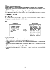
... bigger than actual masking area. 5) During turbo panning or tilting, the privacy zone may shift depending on the location of a moving object directly beneath the dome. Enter the preset command to access the Pan/ Tilt menu. 3. Position the cursor ( ) next to PAN/TILT SETUP and press the OPEN button to access...
... bigger than actual masking area. 5) During turbo panning or tilting, the privacy zone may shift depending on the location of a moving object directly beneath the dome. Enter the preset command to access the Pan/ Tilt menu. 3. Position the cursor ( ) next to PAN/TILT SETUP and press the OPEN button to access...
Instruction Manual
Page 19
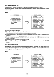
... or to cancel the selection, press the CLOSE button. 6.8.3 SCAN LIMIT STOPS When a Scan Limit Stop is reached during random, frame or auto scan, the dome camera will be slower to keep the image from moving too fast on the monitor. 6.8.2 PROPORTIONAL P/T Proportional P/T controls the pan and tilt speeds according to section...
... or to cancel the selection, press the CLOSE button. 6.8.3 SCAN LIMIT STOPS When a Scan Limit Stop is reached during random, frame or auto scan, the dome camera will be slower to keep the image from moving too fast on the monitor. 6.8.2 PROPORTIONAL P/T Proportional P/T controls the pan and tilt speeds according to section...
Instruction Manual
Page 21
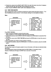
... STOPS OFF PARK TIME MIN 0MIN AUTO PATROL P1ˠOFF SCAN SPEED 5DEG./S SCAN TILT ANGLE 30DEG. Menu MAIN MENU EXIT - 21 - Position the camera for the controller model and preset command. 2. To accept the selection, press the OPEN button or to 720 minutes. If the right limit stop is... The Auto Patrol feature will disable the feature. However, it to 0 will repeat a pattern of up or down to set the number of inactivity, the dome camera will be displayed on screen. 5.
... STOPS OFF PARK TIME MIN 0MIN AUTO PATROL P1ˠOFF SCAN SPEED 5DEG./S SCAN TILT ANGLE 30DEG. Menu MAIN MENU EXIT - 21 - Position the camera for the controller model and preset command. 2. To accept the selection, press the OPEN button or to 720 minutes. If the right limit stop is... The Auto Patrol feature will disable the feature. However, it to 0 will repeat a pattern of up or down to set the number of inactivity, the dome camera will be displayed on screen. 5.

Instruction Manual
Page 23
6.8.8 SCAN TILT ANGLE The tilt angle of the dome camera for auto scan, random scan and frame scan can be set from 1 sec to 60 sec can be set. Refer to section 6.1 for the specified ... STOPS OFF MANUAL LIMIT STOPS OFF PARK TIME MIN 0MIN AUTO PATROL P1ˠOFF SCAN SPEED 5DEG./S SCAN TILT ANGLE 30DEG. During scanning, the camera will not move the cursor to set SCAN TILT ANGLE: 1. Position the cursor next to SCAN TILT ANGLE and press the OPEN button to move...
6.8.8 SCAN TILT ANGLE The tilt angle of the dome camera for auto scan, random scan and frame scan can be set from 1 sec to 60 sec can be set. Refer to section 6.1 for the specified ... STOPS OFF MANUAL LIMIT STOPS OFF PARK TIME MIN 0MIN AUTO PATROL P1ˠOFF SCAN SPEED 5DEG./S SCAN TILT ANGLE 30DEG. During scanning, the camera will not move the cursor to set SCAN TILT ANGLE: 1. Position the cursor next to SCAN TILT ANGLE and press the OPEN button to move...

Instruction Manual
Page 26
... to access the menu. 3. AUTO SCAN: The dome camera performs an auto scan operation. FRAME SCAN: The dome camera performs a frame scan operation. RANDOM SCAN: The dome camera performs a random scan operation. AUTO PATROL: The dome camera performs an auto patrol operation. Position the cursor ( ) next to OTHERS...Refer to the right. 4. Enter the preset command to Preset 1 position. PARK: The dome camera moves to access the main menu. 6.10 OTHERS MENU 6.10.1 POWER UP During Power-Up, the dome camera can be set to cancel the selection, press the CLOSE button. - 26 - To ...
... to access the menu. 3. AUTO SCAN: The dome camera performs an auto scan operation. FRAME SCAN: The dome camera performs a frame scan operation. RANDOM SCAN: The dome camera performs a random scan operation. AUTO PATROL: The dome camera performs an auto patrol operation. Position the cursor ( ) next to OTHERS...Refer to the right. 4. Enter the preset command to Preset 1 position. PARK: The dome camera moves to access the main menu. 6.10 OTHERS MENU 6.10.1 POWER UP During Power-Up, the dome camera can be set to cancel the selection, press the CLOSE button. - 26 - To ...

Instruction Manual
Page 27
... not be loaded. Refer to cancel the selection, press the CLOSE button. 6.10.3 LOAD FACTORY DEFAULTS The factory default settings can be shown while the dome camera moves from the current position to ON or OFF. 5. To accept the selection, press the OPEN button or to section 6.1 for the controller model and...
... not be loaded. Refer to cancel the selection, press the CLOSE button. 6.10.3 LOAD FACTORY DEFAULTS The factory default settings can be shown while the dome camera moves from the current position to ON or OFF. 5. To accept the selection, press the OPEN button or to section 6.1 for the controller model and...

Instruction Manual
Page 33
...OFF POWER TERMINAL BNC Connector - 33 - In daisy chain operation system, the farthest dome from a controller is turned ON. The other dome camera is turned OFF. (It is RS422 termination switch located near the BNC connector. Camera Address = 1 × bit 1 Status + 2 x bit 2 Status + ...TOSHIBA-D On Off Reserve1 Off On Reserve2 On On (3) SW2 (bit3 - 4) Bit Rate Protocol 1200bps 2400bps 4800bps 9600bps bit3 bit4 Off Off On Off Off On On On (Dome base switch:S301) This is OFF at the time of shipment.) ON and OFF are as in the direct mode, the only furthest dome camera...
...OFF POWER TERMINAL BNC Connector - 33 - In daisy chain operation system, the farthest dome from a controller is turned ON. The other dome camera is turned OFF. (It is RS422 termination switch located near the BNC connector. Camera Address = 1 × bit 1 Status + 2 x bit 2 Status + ...TOSHIBA-D On Off Reserve1 Off On Reserve2 On On (3) SW2 (bit3 - 4) Bit Rate Protocol 1200bps 2400bps 4800bps 9600bps bit3 bit4 Off Off On Off Off On On On (Dome base switch:S301) This is OFF at the time of shipment.) ON and OFF are as in the direct mode, the only furthest dome camera...
Instruction Manual
Page 34
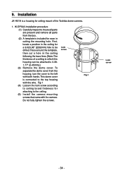
.... IK-DP30A Installation procedure (1) Carefully inspect to insure all parts are present and remove all parts from the housing, turn the cover to be attached is included for ceiling mount of a ceiling to the ceiling. (5) Install the camera mounting screws that came with the camera...., locate a position in the ceiling following the trace lines. [Note: The thickness of the Toshiba dome camera. 1. To separate the dome cover from the box. (2) A template is 0.081.77" (2-45mm).] (3) Remove the dome cover. Fig-1 (4) Loosen the lock screw according to ceiling board thickness for a 9.020.08...
.... IK-DP30A Installation procedure (1) Carefully inspect to insure all parts are present and remove all parts from the housing, turn the cover to be attached is included for ceiling mount of a ceiling to the ceiling. (5) Install the camera mounting screws that came with the camera...., locate a position in the ceiling following the trace lines. [Note: The thickness of the Toshiba dome camera. 1. To separate the dome cover from the box. (2) A template is 0.081.77" (2-45mm).] (3) Remove the dome cover. Fig-1 (4) Loosen the lock screw according to ceiling board thickness for a 9.020.08...
Instruction Manual
Page 36
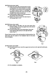
...-5 (IK-DP30A dome drive install) (14) After setting up the notch with both hands. (IK-DP30A dome base install) (11) Attach the video cable (included with both q hands. Fig-6 w Ensure that the location of the notch (position of yellow paint) on the w dome base and the location of a dome base. [Note: Do not connect a thick coaxial cable to a dome camera.
...-5 (IK-DP30A dome drive install) (14) After setting up the notch with both hands. (IK-DP30A dome base install) (11) Attach the video cable (included with both q hands. Fig-6 w Ensure that the location of the notch (position of yellow paint) on the w dome base and the location of a dome base. [Note: Do not connect a thick coaxial cable to a dome camera.
Instruction Manual
Page 40
In order to take advantage of this CCD Camera model IK-DP30A("Product"). Before seeking warranty service, you discover that this Product will perform in accordance with additional packing material before operating this Product...purchase at (877) 855-1349 to receive a RMA number: and (b) pay all transportation and insurance costs. LIMITED WARRANTY CCD SECURITY DOME CAMERA IK-DP30A The Imaging System Division ("ISD") of Toshiba America Information Systems, Inc makes the following conditions: 1. You should read the Instruction Manual (Owner's Manual) thoroughly before shipping the ...
In order to take advantage of this CCD Camera model IK-DP30A("Product"). Before seeking warranty service, you discover that this Product will perform in accordance with additional packing material before operating this Product...purchase at (877) 855-1349 to receive a RMA number: and (b) pay all transportation and insurance costs. LIMITED WARRANTY CCD SECURITY DOME CAMERA IK-DP30A The Imaging System Division ("ISD") of Toshiba America Information Systems, Inc makes the following conditions: 1. You should read the Instruction Manual (Owner's Manual) thoroughly before shipping the ...
