

Service Manual
Page 1
FILE NO. 020-200012 SERVICE MANUAL COLOR TELEVISION N0NSP Chassis 50A60, 50A50 (TAC0050) (TAC0051) 55A60, 61A60 (TAC0052) (TAC0053) Downloaded from www.Manualslib.com manuals search engine PUBLISHED IN JAPAN, May., 2000 S
FILE NO. 020-200012 SERVICE MANUAL COLOR TELEVISION N0NSP Chassis 50A60, 50A50 (TAC0050) (TAC0051) 55A60, 61A60 (TAC0052) (TAC0053) Downloaded from www.Manualslib.com manuals search engine PUBLISHED IN JAPAN, May., 2000 S
Service Manual
Page 2
...ADJUSTMENTS SPECIFIC INFORMATIONS TABLE OF CONTENTS CHAPTER 1 GENERAL ADJUSTMENTS SAFETY INSTRUCTIONS ...3 CRT ASSEMBLY REPLACEMENT AND MOUNTING 4 PICTURE TUBE COMPONENTS ADJUSTMENT ...6 REPLACEMENT OF THE CRT ...8 SERVICE MODE ...9 ELECTRICAL ADJUSTMENT ...11 CONVERGENCE ADJUSTMENT ...13 SCREEN AND MIRROR ALIGNMENTS ...15 CIRCUIT CHECKS ...16 CHAPTER 2 SPECIFIC INFORMATIONS SETTING & ADJUSTING DATA ...17 LOCATION......25 PC BOARDS BOTTOM VIEW ...41 TERMINAL VIEW OF TRANSISTORS ...51 SPECIFICATIONS ...53 APPENDIX: CIRCUIT DIAGRAM Downloaded from www.Manualslib.com manuals search engine - 2 -
...ADJUSTMENTS SPECIFIC INFORMATIONS TABLE OF CONTENTS CHAPTER 1 GENERAL ADJUSTMENTS SAFETY INSTRUCTIONS ...3 CRT ASSEMBLY REPLACEMENT AND MOUNTING 4 PICTURE TUBE COMPONENTS ADJUSTMENT ...6 REPLACEMENT OF THE CRT ...8 SERVICE MODE ...9 ELECTRICAL ADJUSTMENT ...11 CONVERGENCE ADJUSTMENT ...13 SCREEN AND MIRROR ALIGNMENTS ...15 CIRCUIT CHECKS ...16 CHAPTER 2 SPECIFIC INFORMATIONS SETTING & ADJUSTING DATA ...17 LOCATION......25 PC BOARDS BOTTOM VIEW ...41 TERMINAL VIEW OF TRANSISTORS ...51 SPECIFICATIONS ...53 APPENDIX: CIRCUIT DIAGRAM Downloaded from www.Manualslib.com manuals search engine - 2 -

Service Manual
Page 3
...exposed metallic parts of the cabinet, such as specified in this check). The only source of this receiver is serviced, the FS circuit must be observed before servicing this manual. 3. The picture tube is the picture tube. Use shatter proof goggles and keep picture tube away from ...www.Manualslib.com manuals search engine - 3 - to 0.2 milliamp. Reverse the AC plug at the AC outlet and repeat AC voltage measurements for...
...exposed metallic parts of the cabinet, such as specified in this check). The only source of this receiver is serviced, the FS circuit must be observed before servicing this manual. 3. The picture tube is the picture tube. Use shatter proof goggles and keep picture tube away from ...www.Manualslib.com manuals search engine - 3 - to 0.2 milliamp. Reverse the AC plug at the AC outlet and repeat AC voltage measurements for...

Service Manual
Page 5
... area) TSE3843W #23960136 15 ~ 25 mm 2 ~ 5 mm SPECIFIC INFORMATIONS SERVICING PRECAUTIONS s Do not use a magnetized screw driver for SVM coil Downloaded from CRT. 2. YOKE from www.Manualslib.com manuals search engine - 5 - GENERAL ADJUSTMENTS TO REMOVE CRT (Same procedure for .... 1. Remove Lens Assembly. 3. USER CONVERGENCE CENTER CHECK (See owner's manual.) 4. M. PICTURE TILT ADJUSTMENT (page 6.) 3. s When replacing the anode cap assembly (CRT) or anode lead assembly (F.B.T.), remove the anode lead holder from old one . See "SERVICING PRECAUTIONS" shown below. 2.
... area) TSE3843W #23960136 15 ~ 25 mm 2 ~ 5 mm SPECIFIC INFORMATIONS SERVICING PRECAUTIONS s Do not use a magnetized screw driver for SVM coil Downloaded from CRT. 2. YOKE from www.Manualslib.com manuals search engine - 5 - GENERAL ADJUSTMENTS TO REMOVE CRT (Same procedure for .... 1. Remove Lens Assembly. 3. USER CONVERGENCE CENTER CHECK (See owner's manual.) 4. M. PICTURE TILT ADJUSTMENT (page 6.) 3. s When replacing the anode cap assembly (CRT) or anode lead assembly (F.B.T.), remove the anode lead holder from old one . See "SERVICING PRECAUTIONS" shown below. 2.

Service Manual
Page 6
...pat- tern center comes to secure Lens Assembly. 2. Repeat steps 3 to adjust the fastening screw (Fig. Downloaded from www.Manualslib.com manuals search engine Stretch a thread between two center slots of green line. 10. a.) 2. play the white cross-bar. 4. Perform HEIGHT ...so that the cross-bar pat- GENERAL ADJUSTMENTS SPECIFIC INFORMATIONS WARNING : BEFORE SERVICING THIS CHASSIS, READ THE "X-RAY RADIATION PRECAUTION", "SAFETY PRECAUTION" AND "PRODUCT SAFETY NOTICE" ON PAGE 3 OF THIS MANUAL. Perform VERT. tern center comes to erase Blue color 5. Select the adjustment...
...pat- tern center comes to secure Lens Assembly. 2. Repeat steps 3 to adjust the fastening screw (Fig. Downloaded from www.Manualslib.com manuals search engine Stretch a thread between two center slots of green line. 10. a.) 2. play the white cross-bar. 4. Perform HEIGHT ...so that the cross-bar pat- GENERAL ADJUSTMENTS SPECIFIC INFORMATIONS WARNING : BEFORE SERVICING THIS CHASSIS, READ THE "X-RAY RADIATION PRECAUTION", "SAFETY PRECAUTION" AND "PRODUCT SAFETY NOTICE" ON PAGE 3 OF THIS MANUAL. Perform VERT. tern center comes to erase Blue color 5. Select the adjustment...

Service Manual
Page 8
...LEAD AND ANODE CAP. b Cut here rubber boot and lead together to detach Lead Holder. HITACHI CRT 50A50 50A60 55A60 61A60 R 23796001 23005114 23005242 23005249 G 23005397 23005115 ↑ ↑ B 23796003 ↑ ↑...IS ATTACHED TO ANODE LEAD AND ANODE CAP. 2. GENERAL ADJUSTMENTS SPECIFIC INFORMATIONS REPLACEMENT OF THE CRT Service parts are as shown in figure below, and put it on new lead. Do not throw...Anode Cap with new one, remove Lead Holder from www.Manualslib.com manuals search engine - 8 - Downloaded from old lead as follows. Detaching Lead Holder RUBBER BOOT OLD ANODE...
...LEAD AND ANODE CAP. b Cut here rubber boot and lead together to detach Lead Holder. HITACHI CRT 50A50 50A60 55A60 61A60 R 23796001 23005114 23005242 23005249 G 23005397 23005115 ↑ ↑ B 23796003 ↑ ↑...IS ATTACHED TO ANODE LEAD AND ANODE CAP. 2. GENERAL ADJUSTMENTS SPECIFIC INFORMATIONS REPLACEMENT OF THE CRT Service parts are as shown in figure below, and put it on new lead. Do not throw...Anode Cap with new one, remove Lead Holder from www.Manualslib.com manuals search engine - 8 - Downloaded from old lead as follows. Detaching Lead Holder RUBBER BOOT OLD ANODE...

Service Manual
Page 9
.../OFF (1kHz) : Self diagnostic display : 1 button 2 button 3 button 4 button 5 button 6 button 7 button 8 button 9 button Downloaded from www.Manualslib.com manuals search engine - 9 - Screen adjustment mode ON/OFF: Selection of the adjustment items : Change of the data value : Adjustment menu mode ON/OFF : Initialization of the... MUTE button again to keep pressing. 3) While pressing the MUTE button, press MENU button on Remote Control. KEY FUNCTION IN THE SERVICE MODE The following key entry during display of the self diagnostic data: TV (ANT)/VIDEO button (on TV) Channel s/t (on TV...
.../OFF (1kHz) : Self diagnostic display : 1 button 2 button 3 button 4 button 5 button 6 button 7 button 8 button 9 button Downloaded from www.Manualslib.com manuals search engine - 9 - Screen adjustment mode ON/OFF: Selection of the adjustment items : Change of the data value : Adjustment menu mode ON/OFF : Initialization of the... MUTE button again to keep pressing. 3) While pressing the MUTE button, press MENU button on Remote Control. KEY FUNCTION IN THE SERVICE MODE The following key entry during display of the self diagnostic data: TV (ANT)/VIDEO button (on TV) Channel s/t (on TV...

Service Manual
Page 10
...of protection circuit (current limiter) . . . . SELECTING THE ADJUSTING ITEMS 1) Every pressing of CHANNEL s button in the service mode changes the adjustment items in the range from www.Manualslib.com manuals search engine - 10 - ADJUSTING THE DATA 1) Pressing of VOLUME s or t button will begin to FFH. The variable... range depends on the owner's manual. s INITIALIZATION OF MEMORY DATA OF QA02 After replacing QA02, the following displays are plural. Press and hold the RECALL button on the ...
...of protection circuit (current limiter) . . . . SELECTING THE ADJUSTING ITEMS 1) Every pressing of CHANNEL s button in the service mode changes the adjustment items in the range from www.Manualslib.com manuals search engine - 10 - ADJUSTING THE DATA 1) Pressing of VOLUME s or t button will begin to FFH. The variable... range depends on the owner's manual. s INITIALIZATION OF MEMORY DATA OF QA02 After replacing QA02, the following displays are plural. Press and hold the RECALL button on the ...
Service Manual
Page 11
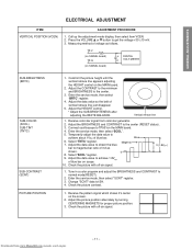
...bar on the screen. 2. TP-V (on SIGNAL board) TP-G (on the MAIN board. 2. Enter the service mode, then select "BRTC" register. 4. Receive color-bar signal from www.Manualslib.com manuals search engine - 11 - Change "SCNT" data to13H. 4. Check the picture with off -air signal. Enter... the service mode, then select "SCOL". 5. Adjust the data value to obtain the blue bar to the center. 3. ...
...bar on the screen. 2. TP-V (on SIGNAL board) TP-G (on the MAIN board. 2. Enter the service mode, then select "BRTC" register. 4. Receive color-bar signal from www.Manualslib.com manuals search engine - 11 - Change "SCNT" data to13H. 4. Check the picture with off -air signal. Enter... the service mode, then select "SCOL". 5. Adjust the data value to obtain the blue bar to the center. 3. ...

Service Manual
Page 12
..., then adjust the data of FOCUS PAC (page 7) clock- Press TV (ANT)/VIDEO button on TV again. 6. Exit from www.Manualslib.com manuals search engine - 12 - Check the white balance in order to high light. 10. Call up the adjustment mode display, then select the item VLIN...to the minimum to make white picture to check the raster.) 5. Adjust the contrast to the maximum to make white picture to "40". 3. Downloaded from service mode. 7. Then readjust the item HIT. Center WHITE BALANCE (RCUT) (GCUT) (BCUT) (RDRV) (BDRV) 1. wise or counterclockwise until the raster ...
..., then adjust the data of FOCUS PAC (page 7) clock- Press TV (ANT)/VIDEO button on TV again. 6. Exit from www.Manualslib.com manuals search engine - 12 - Check the white balance in order to high light. 10. Call up the adjustment mode display, then select the item VLIN...to the minimum to make white picture to check the raster.) 5. Adjust the contrast to the maximum to make white picture to "40". 3. Downloaded from service mode. 7. Then readjust the item HIT. Center WHITE BALANCE (RCUT) (GCUT) (BCUT) (RDRV) (BDRV) 1. wise or counterclockwise until the raster ...

Service Manual
Page 16
... on to reset. Turn the receiver on page17) NO Defective Fail Safe Circuit Downloaded from www.Manualslib.com manuals search engine - 16 - Checking should be measured below . High voltages are also present in servicing. CAUTION: When the following the steps below . 1. YES NO Check the voltage across Capacitor C471 is functioning properly...
... on to reset. Turn the receiver on page17) NO Defective Fail Safe Circuit Downloaded from www.Manualslib.com manuals search engine - 16 - Checking should be measured below . High voltages are also present in servicing. CAUTION: When the following the steps below . 1. YES NO Check the voltage across Capacitor C471 is functioning properly...

Service Manual
Page 17
... 55", 61" HIGH VOLTAGE AT ZERO BEAM: (A) 31.3 kV MAX HIGH VOLTAGE: (B) 32.4 kV Table-1 ADJUSTING ITEMS AND DATA IN THE SERVICE MODE: Item Name of adjustment Preset Date VCP V-COMPENSATE 0AH ← PARA E-W PARABOLA (DPC) 29H ← CNR E-W CORNER 08H ← ...; VCEN V POSITION 81H ← TVOP TV OPTION 00H ← Table-2 CIRCUIT CHECKS FBT DETECTION VOLTAGE (C) 24.5V Table-3 Downloaded from www.Manualslib.com manuals search engine - 17 - POSITION VERT. POSITION HEIGHT V-LINEARITY V-S CORRECTION PICTURE WIDTH V-SHIFT 40H ← 40H ← 40H ← 40H ← ...
... 55", 61" HIGH VOLTAGE AT ZERO BEAM: (A) 31.3 kV MAX HIGH VOLTAGE: (B) 32.4 kV Table-1 ADJUSTING ITEMS AND DATA IN THE SERVICE MODE: Item Name of adjustment Preset Date VCP V-COMPENSATE 0AH ← PARA E-W PARABOLA (DPC) 29H ← CNR E-W CORNER 08H ← ...; VCEN V POSITION 81H ← TVOP TV OPTION 00H ← Table-2 CIRCUIT CHECKS FBT DETECTION VOLTAGE (C) 24.5V Table-3 Downloaded from www.Manualslib.com manuals search engine - 17 - POSITION VERT. POSITION HEIGHT V-LINEARITY V-S CORRECTION PICTURE WIDTH V-SHIFT 40H ← 40H ← 40H ← 40H ← ...

Service Manual
Page 23
... PF, 3.3?F, ±10%, 100V PF, 0.047?F, 200V CD, 220pF, ±10%, 500V PF, 0.47?F, 400V Downloaded from www.Manualslib.com manuals search engine - 25 - NOTICE: • The part number must be used when ordering parts, in order to assist in processing, be identical with ...C407 * C408 C410 C412 C413 * C414 Part No. Before replacing any of the receiver through improper servicing. Do not degrade the safety of these components, read carefully the PRODUCT SAFETY NOTICE. Models : 50A60/50A50/55A60/61A60 Capacitors CD : Ceramic Disk PF : Plastic Film EL : Resistors CF : Carbon...
... PF, 3.3?F, ±10%, 100V PF, 0.047?F, 200V CD, 220pF, ±10%, 500V PF, 0.47?F, 400V Downloaded from www.Manualslib.com manuals search engine - 25 - NOTICE: • The part number must be used when ordering parts, in order to assist in processing, be identical with ...C407 * C408 C410 C412 C413 * C414 Part No. Before replacing any of the receiver through improper servicing. Do not degrade the safety of these components, read carefully the PRODUCT SAFETY NOTICE. Models : 50A60/50A50/55A60/61A60 Capacitors CD : Ceramic Disk PF : Plastic Film EL : Resistors CF : Carbon...

