
Operation Manual
Page 1
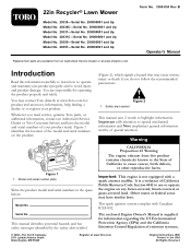
... or federal areas may cause serious injury or death if you need service, genuine Toro parts, or additional information, contact an Authorized Service Dealer or Toro Customer Service and have similar laws. This manual identifies potential hazards and has safety messages identified by the safety alert ...Service Dealer or at www.Toro.com. Figure 1 identifies the location of California to use or operate the engine on the product. (Figure 2), which signals a hazard that may have the model and serial numbers of special attention. 22in Recycler® Lawn Mower Model No. 20330...
... or federal areas may cause serious injury or death if you need service, genuine Toro parts, or additional information, contact an Authorized Service Dealer or Toro Customer Service and have similar laws. This manual identifies potential hazards and has safety messages identified by the safety alert ...Service Dealer or at www.Toro.com. Figure 1 identifies the location of California to use or operate the engine on the product. (Figure 2), which signals a hazard that may have the model and serial numbers of special attention. 22in Recycler® Lawn Mower Model No. 20330...
Operation Manual
Page 4
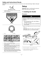
...danger. Remove the handle knobs from the machine. 3. Thrown object hazard-keep bystanders a safe distance from the mower housing (Figure 3). Indicates the blade is damaged, contact an Authorized Service Dealer. 1. Unlock Folding or unfolding the handle improperly can damage the cables, causing an unsafe operating condition. &#...as a part from the original machine manufacturer. Setup Manufacturer's Mark 1. operate side to the outside of hand or foot, mower blade-remove the ignition key and read the Operator's Manual. 2. Figure 3 2. Move the handle to the operating position. 3.
...danger. Remove the handle knobs from the machine. 3. Thrown object hazard-keep bystanders a safe distance from the mower housing (Figure 3). Indicates the blade is damaged, contact an Authorized Service Dealer. 1. Unlock Folding or unfolding the handle improperly can damage the cables, causing an unsafe operating condition. &#...as a part from the original machine manufacturer. Setup Manufacturer's Mark 1. operate side to the outside of hand or foot, mower blade-remove the ignition key and read the Operator's Manual. 2. Figure 3 2. Move the handle to the operating position. 3.
Operation Manual
Page 11
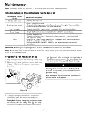
...8226; Clean grass clippings and dirt from an Authorized Service Dealer (go to www.toro.com to the spark plug. Tipping the mower may cause the fuel to run dry through normal usage. Important: Before tipping the mower to change the oil or replace the blade, allow...procedures. Figure 14 3. Important: Refer to stop. 2. Preparing for all moving parts to your engine operator's manual for additional maintenance procedures. Recommended Maintenance Schedule(s) Maintenance Service Interval After the first 5 hours Before each use a hand fuel pump to remove the fuel. Disconnect the spark...
...8226; Clean grass clippings and dirt from an Authorized Service Dealer (go to www.toro.com to the spark plug. Tipping the mower may cause the fuel to run dry through normal usage. Important: Before tipping the mower to change the oil or replace the blade, allow...procedures. Figure 14 3. Important: Refer to stop. 2. Preparing for all moving parts to your engine operator's manual for additional maintenance procedures. Recommended Maintenance Schedule(s) Maintenance Service Interval After the first 5 hours Before each use a hand fuel pump to remove the fuel. Disconnect the spark...
Operation Manual
Page 16
... other remedies fail, you are warranted for any Authorized Toro Service Dealer to all 22 in Recycler® walk power mowers. General Conditions All repairs covered by these warranties must maintain your Operator's Manual if in materials or workmanship or if it is de...commercial use pending completion of repairs under The Toro Total Coverage Guarantee The Toro Company and its affiliate, Toro Warranty Company, pursuant to the Service Dealer. or call the numbers listed in Recycler® Walk Power Mowers Conditions and Products Covered under these warranties. ...
... other remedies fail, you are warranted for any Authorized Toro Service Dealer to all 22 in Recycler® walk power mowers. General Conditions All repairs covered by these warranties must maintain your Operator's Manual if in materials or workmanship or if it is de...commercial use pending completion of repairs under The Toro Total Coverage Guarantee The Toro Company and its affiliate, Toro Warranty Company, pursuant to the Service Dealer. or call the numbers listed in Recycler® Walk Power Mowers Conditions and Products Covered under these warranties. ...

Service Manual
Page 1
WALK BEHIND POWER MOWER DRIVE SYSTEMS SERVICE MANUAL
WALK BEHIND POWER MOWER DRIVE SYSTEMS SERVICE MANUAL
Service Manual
Page 3
...; All Rights Reserved ©2006 The Toro Company This book contains material covering the Toro and Lawn-Boy Walk Behind Mower Drive Systems models from 1990 through 2006, and may be specified for Toro servicing dealers. We are similar in this manual complete and correct. ABOUT THIS MANUAL This service manual was written with the assumption that you...
...; All Rights Reserved ©2006 The Toro Company This book contains material covering the Toro and Lawn-Boy Walk Behind Mower Drive Systems models from 1990 through 2006, and may be specified for Toro servicing dealers. We are similar in this manual complete and correct. ABOUT THIS MANUAL This service manual was written with the assumption that you...
Service Manual
Page 6
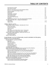
... AXLE & TRANSMISSION ASSEMBLY 3-4 22" FRONT WHEEL DRIVE MODELS Remove Transmission 3-5 Transmission Disassembly 3-7 Transmission Assembly 3-7 Assembly Tips 3-8 Belt Service - Front Wheel Drive Models 3-9 22" TORO & LAWN-BOY REAR WHEEL DRIVE MODELS Transmission Removal & Belt Replacement 3-...4-2 OPERATION Input System 4-3 ii WPM Drive Systems Manual TABLE OF CONTENTS WORM DRIVE TRANSMISSION GENERAL INTERNALLY CLUTCHED Description 1-2 Lubrication 1-3 The Shifting Process 1-3 Removal & Installation (front wheel drive applications 1-4 Disassembly 1-5 Assembly 1-7 Controls 1-9 ...
... AXLE & TRANSMISSION ASSEMBLY 3-4 22" FRONT WHEEL DRIVE MODELS Remove Transmission 3-5 Transmission Disassembly 3-7 Transmission Assembly 3-7 Assembly Tips 3-8 Belt Service - Front Wheel Drive Models 3-9 22" TORO & LAWN-BOY REAR WHEEL DRIVE MODELS Transmission Removal & Belt Replacement 3-...4-2 OPERATION Input System 4-3 ii WPM Drive Systems Manual TABLE OF CONTENTS WORM DRIVE TRANSMISSION GENERAL INTERNALLY CLUTCHED Description 1-2 Lubrication 1-3 The Shifting Process 1-3 Removal & Installation (front wheel drive applications 1-4 Disassembly 1-5 Assembly 1-7 Controls 1-9 ...
Service Manual
Page 7
... Style 5-9 Servicing the System 5-9 WHEEL PINION SERVICE 5-9 BLADE BRAKE CLUTCH SYSTEMS (BBC), BLADE OVERRIDE SYSTEM (BOS), BLADE CLUTCH SYSTEM (BCS) BLADE BRAKE CLUTCH SYSTEM Description 6-2 BBC Clutch Option 6-2 Control Box Operation 6-2 Handle Controls 6-3 Control Box Disassembly 6-6 Control Box Assembly 6-7 TORO BBC SERVICE GUIDE 6-10 BLADE BRAKE CLUTCH ASSEMBLY (Toro Vacu Power/Lawn-Boy Medallion 6-11 TORO VACU POWER/LAWN...
... Style 5-9 Servicing the System 5-9 WHEEL PINION SERVICE 5-9 BLADE BRAKE CLUTCH SYSTEMS (BBC), BLADE OVERRIDE SYSTEM (BOS), BLADE CLUTCH SYSTEM (BCS) BLADE BRAKE CLUTCH SYSTEM Description 6-2 BBC Clutch Option 6-2 Control Box Operation 6-2 Handle Controls 6-3 Control Box Disassembly 6-6 Control Box Assembly 6-7 TORO BBC SERVICE GUIDE 6-10 BLADE BRAKE CLUTCH ASSEMBLY (Toro Vacu Power/Lawn-Boy Medallion 6-11 TORO VACU POWER/LAWN...
Service Manual
Page 9
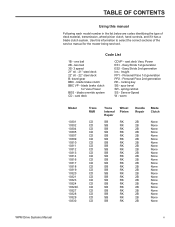
blade brake clutch BBC VP - blade brake clutch for the mower being serviced. Personal Pace 1st generation PP2 - rocking key SB - spring ratchet SS - worm ...CD CD CD CD CD CD CD CD CD CD CD CD CD CD CD CD Trans Internal Repair Wheel Pinion SB RK SB RK SB RK SB RK SB RK SB RK SB RK SB RK SB RK...cast deck CDVP - Easy Stride 1st generation ES2 - spur bevel SR - Use this manual Following each model number in the list below are codes identifying the type of the service manual for Vacu Power BOS - Insight PP1 - Personal Pace 2nd generation RK - two bail 3S- 3 speed...
blade brake clutch BBC VP - blade brake clutch for the mower being serviced. Personal Pace 1st generation PP2 - rocking key SB - spring ratchet SS - worm ...CD CD CD CD CD CD CD CD CD CD CD CD CD CD CD CD Trans Internal Repair Wheel Pinion SB RK SB RK SB RK SB RK SB RK SB RK SB RK SB RK SB RK...cast deck CDVP - Easy Stride 1st generation ES2 - spur bevel SR - Use this manual Following each model number in the list below are codes identifying the type of the service manual for Vacu Power BOS - Insight PP1 - Personal Pace 2nd generation RK - two bail 3S- 3 speed...
Service Manual
Page 47
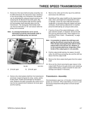
Drain the fuel and oil and tip the mower on the wheel clutch see Section 5, Wheel Pinion Clutch. Identify right and left from under the housing (...R and L for right and left side. Front Wheel Drive Models To replace the self-propelled drive belt, proceed as follows: 1. The letter L should face out. The wheel pinion is marked with #2 molybendum disulfide base... the belt off the transmission pulley and push it towards the engine (Fig. 058). If the wheel pinions are reversed, the wheels will not drive. Remove the two screws securing the belt cover from the operator's position (Fig....
Drain the fuel and oil and tip the mower on the wheel clutch see Section 5, Wheel Pinion Clutch. Identify right and left from under the housing (...R and L for right and left side. Front Wheel Drive Models To replace the self-propelled drive belt, proceed as follows: 1. The letter L should face out. The wheel pinion is marked with #2 molybendum disulfide base... the belt off the transmission pulley and push it towards the engine (Fig. 058). If the wheel pinions are reversed, the wheels will not drive. Remove the two screws securing the belt cover from the operator's position (Fig....
Service Manual
Page 52
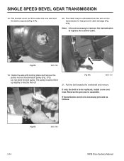
... arm on the transmission to replace the control cable. Reverse the process to slip the belt off. If transmission service is exposed (Fig. 074). 20. Fig 075 MVC-740 3-14 WPM Drive Systems Manual The cable may be replaced, install a new one now. Note: It is not necessary to remove the transmission...
... arm on the transmission to replace the control cable. Reverse the process to slip the belt off. If transmission service is exposed (Fig. 074). 20. Fig 075 MVC-740 3-14 WPM Drive Systems Manual The cable may be replaced, install a new one now. Note: It is not necessary to remove the transmission...
Service Manual
Page 64
... On the right side, the R should face outward on the mower together. 6. The best way is properly seated in the chassis to secure the cover. see Handles & Control Cables. 3-26 WPM Drive Systems Manual The wheel pinion is retained with screws (Fig. 113). The letter L should...washer is to declutch properly. A R B Fig 112 MVC-474 A. Note: Wheel Clutch Service - see Spring Ratchet Key Style Clutch, page 5-8. SINGLE SPEED BEVEL GEAR TRANSMISSION 4. If the wheel pinions are reversed, the wheels will not drive. 7. Do not use an impact wrench on the back side ...
... On the right side, the R should face outward on the mower together. 6. The best way is properly seated in the chassis to secure the cover. see Handles & Control Cables. 3-26 WPM Drive Systems Manual The wheel pinion is retained with screws (Fig. 113). The letter L should...washer is to declutch properly. A R B Fig 112 MVC-474 A. Note: Wheel Clutch Service - see Spring Ratchet Key Style Clutch, page 5-8. SINGLE SPEED BEVEL GEAR TRANSMISSION 4. If the wheel pinions are reversed, the wheels will not drive. 7. Do not use an impact wrench on the back side ...
Service Manual
Page 71
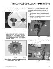
...from the top of the input shaft and pulley assembly can then be held with grease to turn as a lubricant. If service of any of -Cut and Wheel Pinion Clutch - Be careful not to the output shaft. Remove the intermediate shaft from the output shaft. 9. Inspect all ...components for wear, cracks, and/or broken teeth. WPM Drive Systems Manual 4-7 Check the input shaft ball bearing for excessive wear. A B A. 25-tooth...
...from the top of the input shaft and pulley assembly can then be held with grease to turn as a lubricant. If service of any of -Cut and Wheel Pinion Clutch - Be careful not to the output shaft. Remove the intermediate shaft from the output shaft. 9. Inspect all ...components for wear, cracks, and/or broken teeth. WPM Drive Systems Manual 4-7 Check the input shaft ball bearing for excessive wear. A B A. 25-tooth...
Service Manual
Page 73
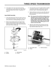
... locknut finger tight. 3. A. Pulley B. Intermediate shaft B. If the input bearing was removed for servicing, reassemble now as shown in step 3, under "Rear Heightof-Cut and Wheel Pinion Clutch - Note: The long end of the shift fork shaft should go through the ball bearing and...C. Input Shaft Assembly 1. Slide the input shaft and pinion through the hole in the proper locations. Shift fork retainer WPM Drive Systems Manual 4-9 Pinion Fig. 100 Fig 127 3428-0059 A. THREE SPEED TRANSMISSION 8. Note that the output bushings are trapped in the gearcase. Slide...
... locknut finger tight. 3. A. Pulley B. Intermediate shaft B. If the input bearing was removed for servicing, reassemble now as shown in step 3, under "Rear Heightof-Cut and Wheel Pinion Clutch - Note: The long end of the shift fork shaft should go through the ball bearing and...C. Input Shaft Assembly 1. Slide the input shaft and pinion through the hole in the proper locations. Shift fork retainer WPM Drive Systems Manual 4-9 Pinion Fig. 100 Fig 127 3428-0059 A. THREE SPEED TRANSMISSION 8. Note that the output bushings are trapped in the gearcase. Slide...
Service Manual
Page 80
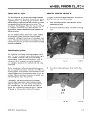
...with shoulder bolt, spacers, wheel cover, and nylon locknut. 5-4 WPM Drive Systems Manual Use #2 lithium grease and only one or the other do not engage or disengage properly try greasing the pivot arm. To operate this time the mower can be serviced with minimal effort. It ... or both engage they are disengaging properly, stop walking, keep your elbows at a normal pace. WHEEL PINION CLUTCH 17. Test for Function Function The rocking keys provide a differential action by engaging and disengaging each drive wheel individually. Disassembly The rear height-of the key ...
...with shoulder bolt, spacers, wheel cover, and nylon locknut. 5-4 WPM Drive Systems Manual Use #2 lithium grease and only one or the other do not engage or disengage properly try greasing the pivot arm. To operate this time the mower can be serviced with minimal effort. It ... or both engage they are disengaging properly, stop walking, keep your elbows at a normal pace. WHEEL PINION CLUTCH 17. Test for Function Function The rocking keys provide a differential action by engaging and disengaging each drive wheel individually. Disassembly The rear height-of the key ...
Service Manual
Page 82
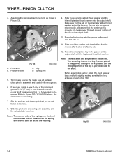
To increase service life, make sure all models use an O-ring. 7. Not all parts are clean prior to ... the clutch washer back and forth slightly, making sure that it is a left and a right wheel pinion key. Fig 139 3428-0028 5-6 WPM Drive Systems Manual Assemble the spring arm and pivot arm as shown in the groove, the top of the key... B D A. Slide the pivot arm and spring arm assembly onto the output shaft, boss first. Place the wheel pinion key in the groove. Refer to the shaft. WHEEL PINION CLUTCH 4. Secure with the leg toward the clutch washer.
To increase service life, make sure all models use an O-ring. 7. Not all parts are clean prior to ... the clutch washer back and forth slightly, making sure that it is a left and a right wheel pinion key. Fig 139 3428-0028 5-6 WPM Drive Systems Manual Assemble the spring arm and pivot arm as shown in the groove, the top of the key... B D A. Slide the pivot arm and spring arm assembly onto the output shaft, boss first. Place the wheel pinion key in the groove. Refer to the shaft. WHEEL PINION CLUTCH 4. Secure with the leg toward the clutch washer.
Service Manual
Page 83
13. Slip the spring onto the end of the clip (Fig. 140). As a rule, use for maximum service life. Install the internally tabbed thrust washer onto the output shaft making sure that may prevent the friction parts from working. Again, make sure that ... to ensure that the center tab fits properly into the keyway to the pivot arm using the nylon locknut. 17. WPM Drive Systems Manual 5-7 Grease with the special retaining clip. WHEEL PINION CLUTCH Fig 140 3428-0040 16. It is symmetrical and can be put on either way. 14. Place the...
13. Slip the spring onto the end of the clip (Fig. 140). As a rule, use for maximum service life. Install the internally tabbed thrust washer onto the output shaft making sure that may prevent the friction parts from working. Again, make sure that ... to ensure that the center tab fits properly into the keyway to the pivot arm using the nylon locknut. 17. WPM Drive Systems Manual 5-7 Grease with the special retaining clip. WHEEL PINION CLUTCH Fig 140 3428-0040 16. It is symmetrical and can be put on either way. 14. Place the...
Service Manual
Page 85
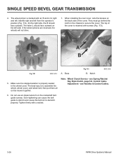
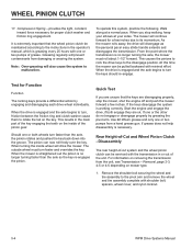
The pinion turns the wheel gear. WHEEL PINION SERVICE The steps to keep the anti seize from drying up. Remove the wheel bolt, wheel and wheel cover (Fig. 142). Lubricate the key, spring, and axle with a block. 2. Fig 142 MVC-739 3. When the mower is off the ground. Support with anti-seize compound...). Make sure the thrust washers have the key tab on a wide variety of the mower, the letter "R" should be two keyed thrust washers and one side and "L" on the pinion. The owner's manual requires that is pulled backwards, this type of the axle, keyway, and the parts ...
The pinion turns the wheel gear. WHEEL PINION SERVICE The steps to keep the anti seize from drying up. Remove the wheel bolt, wheel and wheel cover (Fig. 142). Lubricate the key, spring, and axle with a block. 2. Fig 142 MVC-739 3. When the mower is off the ground. Support with anti-seize compound...). Make sure the thrust washers have the key tab on a wide variety of the mower, the letter "R" should be two keyed thrust washers and one side and "L" on the pinion. The owner's manual requires that is pulled backwards, this type of the axle, keyway, and the parts ...
Service Manual
Page 92
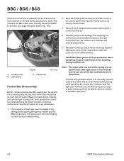
... retaining the 2 control box halves. 4. The first and quickest method is removed. C A B A. Flange nut 3428-0290 Control Box Disassembly NOTE: When servicing the BBC control box, be able to rotate. Wear gloves and eye protection when operating an open control box as it to observe release of...operate the control box while watching for more information. 1. Be careful not to use one of the BBC cable lever. 6-6 WPM Drive Systems Manual CAUTION! Be sure to dislodge any of the spring are malfunctioning. This releases the BBC cable lever, thereby causing the BBC to...
... retaining the 2 control box halves. 4. The first and quickest method is removed. C A B A. Flange nut 3428-0290 Control Box Disassembly NOTE: When servicing the BBC control box, be able to rotate. Wear gloves and eye protection when operating an open control box as it to observe release of...operate the control box while watching for more information. 1. Be careful not to use one of the BBC cable lever. 6-6 WPM Drive Systems Manual CAUTION! Be sure to dislodge any of the spring are malfunctioning. This releases the BBC cable lever, thereby causing the BBC to...
Service Manual
Page 102
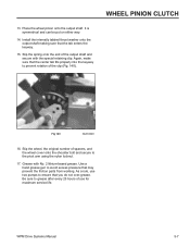
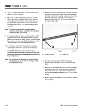
... the brake lever and hub to the brake plate hub and lever and remove the brake plate assembly. If the brake pad has reached its service life or if the brake plate has been damaged, remove the other capscrew securing the brake plate to the housing. The brake pad is under... brake plate counterclockwise and remove the BBC flywheel. 8. Inspect all parts for damage and/or wear and replace as necessary. 6-16 WPM Drive Systems Manual
... the brake lever and hub to the brake plate hub and lever and remove the brake plate assembly. If the brake pad has reached its service life or if the brake plate has been damaged, remove the other capscrew securing the brake plate to the housing. The brake pad is under... brake plate counterclockwise and remove the BBC flywheel. 8. Inspect all parts for damage and/or wear and replace as necessary. 6-16 WPM Drive Systems Manual


