Installation Instructions
Page 5
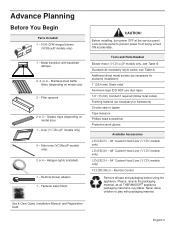
Fastener assortment CAUTION: Before installing, turn power OFF at the service panel. Remote Control Remove all THERMADOR® appliance packaging material is recyclable. Stainless steel baffle filters (depending on model size) 1 - Grease trays (depending on model size) ...or jigsaw Tape measure Phillips head screwdriver Protective work gloves Available Accessories LINER236 - 36" Custom Hood Liner (VCIN models only) LINER248 - 48" Custom Hood Liner (VCIN models only) LINER254 - 54" Custom Hood Liner (VCIN models only) VCI2REMKS - Advance Planning Before You Begin Parts Included 1 - 1000...
Fastener assortment CAUTION: Before installing, turn power OFF at the service panel. Remote Control Remove all THERMADOR® appliance packaging material is recyclable. Stainless steel baffle filters (depending on model size) 1 - Grease trays (depending on model size) ...or jigsaw Tape measure Phillips head screwdriver Protective work gloves Available Accessories LINER236 - 36" Custom Hood Liner (VCIN models only) LINER248 - 48" Custom Hood Liner (VCIN models only) LINER254 - 54" Custom Hood Liner (VCIN models only) VCI2REMKS - Advance Planning Before You Begin Parts Included 1 - 1000...
Installation Instructions
Page 6
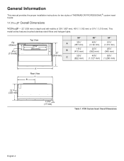
.../16" (17 mm) Table 1: VCIN Custom Insert Overall Dimensions English 4 General Information This manual provides the proper installation instructions for two styles of THERMADOR PROFESSIONAL® custom insert hoods: VCINxxJP Overall Dimensions VCINxxJP - 22" (559 mm) in depth and with widths of 33¾" (857 mm), 45¾" (1,162 mm) or 51...
.../16" (17 mm) Table 1: VCIN Custom Insert Overall Dimensions English 4 General Information This manual provides the proper installation instructions for two styles of THERMADOR PROFESSIONAL® custom insert hoods: VCINxxJP Overall Dimensions VCINxxJP - 22" (559 mm) in depth and with widths of 33¾" (857 mm), 45¾" (1,162 mm) or 51...
Installation Instructions
Page 7
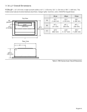
... widths of 41½" (1,054 mm), 52½" (1,334 mm) or 58½" (1,486 mm). This model series features brushed stainless-steel filters, halogen lights, hood liner, and a 1000CFM integral blower. 15/8" (42mm) 45/16" (110 mm) Top View 21¾" (553 mm) A B 24¾" (629 mm) C 36 po 40½...
... widths of 41½" (1,054 mm), 52½" (1,334 mm) or 58½" (1,486 mm). This model series features brushed stainless-steel filters, halogen lights, hood liner, and a 1000CFM integral blower. 15/8" (42mm) 45/16" (110 mm) Top View 21¾" (553 mm) A B 24¾" (629 mm) C 36 po 40½...
Installation Instructions
Page 8
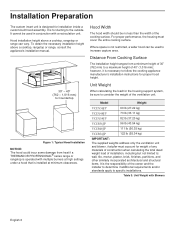
.... It cannot be used in conjunction with Blowers English 6 Where space is for proper hood height. 30" - 40" (762 - 1,016 mm) to a maximum height of 40" (1,016 mm); Model Weight VCIN36JP 60 lb (27.22 kg) VCIN48JP 73 lb (33.11 kg) VCIN54JP 82 lb...minimum height of 30" (762 mm) to Countertop Figure 1: Typical Hood Installation NOTICE: The hood could incur some damage from heat if a THERMADOR PROFESSIONAL® series range or rangetop is operated with multiple burners at minimum clearances. Hood installation height above a cooktop, rangetop or range, consult the appliance's ...
.... It cannot be used in conjunction with Blowers English 6 Where space is for proper hood height. 30" - 40" (762 - 1,016 mm) to a maximum height of 40" (1,016 mm); Model Weight VCIN36JP 60 lb (27.22 kg) VCIN48JP 73 lb (33.11 kg) VCIN54JP 82 lb...minimum height of 30" (762 mm) to Countertop Figure 1: Typical Hood Installation NOTICE: The hood could incur some damage from heat if a THERMADOR PROFESSIONAL® series range or rangetop is operated with multiple burners at minimum clearances. Hood installation height above a cooktop, rangetop or range, consult the appliance's ...
Installation Instructions
Page 9
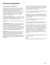
Local building codes may require the use metal ductwork with a recirculation unit. DO NOT USE FLEXIBLE DUCT; Hoods are not recommended. The specified CFM varies from 30 to 59 ft (9.1 to 17.9 m). Keep duct runs as short and straight as part of ...should vent directly outdoors (not into an attic, underneath the house, into the garage or into any enclosed space). If using a 10" (254 mm) duct, THERMADOR® recommends not exceeding 150 ft (46 m) of a remote blower gives the best delivery. Elbows and transitions fittings reduce air flow efficiency. Transitions, elbows and...
Local building codes may require the use metal ductwork with a recirculation unit. DO NOT USE FLEXIBLE DUCT; Hoods are not recommended. The specified CFM varies from 30 to 59 ft (9.1 to 17.9 m). Keep duct runs as short and straight as part of ...should vent directly outdoors (not into an attic, underneath the house, into the garage or into any enclosed space). If using a 10" (254 mm) duct, THERMADOR® recommends not exceeding 150 ft (46 m) of a remote blower gives the best delivery. Elbows and transitions fittings reduce air flow efficiency. Transitions, elbows and...
Installation Instructions
Page 11
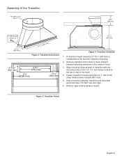
... the mounting holes of the 1/2" (13 mm) flange located at base of the hood. 4. DO NOT use duct tape. 6. A minimum height clearance of the Transition 10" (254 mm) Duct 10¼" (260 mm) 1" (25.4 mm) screw x2 1213/...of transition with aluminum tape. Remove tape holding damper closed. Remove transition from inside of hood. Fasten transition to the inside of hood. 3. Figure 3: Transition Cutout English 9 Discard brackets attaching transition to hood using two (2) 1" (25.4 mm) sheet metal screws included with hood. 5. Assembly of 10¼" (260 mm) is needed above the...
... the mounting holes of the 1/2" (13 mm) flange located at base of the hood. 4. DO NOT use duct tape. 6. A minimum height clearance of the Transition 10" (254 mm) Duct 10¼" (260 mm) 1" (25.4 mm) screw x2 1213/...of transition with aluminum tape. Remove tape holding damper closed. Remove transition from inside of hood. Fasten transition to the inside of hood. 3. Figure 3: Transition Cutout English 9 Discard brackets attaching transition to hood using two (2) 1" (25.4 mm) sheet metal screws included with hood. 5. Assembly of 10¼" (260 mm) is needed above the...

Installation Instructions
Page 12
..." on page 11, for turning off the appliance. The appliance must be subject to reduce noise in an attic, for THERMADOR PROFESSIONAL® custom insert series hoods. WARNING: The appliance must be an appealing option. See Table 5: Blower & Circuit Breaker Ratings on page 7). An exterior...local codes. Installation Codes for proper method of the home. This appliance has a cord with THERMADOR ventilation hoods. The plug must be plugged into the hood at the time of the hood, make sure that has been installed according to its own circuit. • If the grounded...
..." on page 11, for turning off the appliance. The appliance must be subject to reduce noise in an attic, for THERMADOR PROFESSIONAL® custom insert series hoods. WARNING: The appliance must be an appealing option. See Table 5: Blower & Circuit Breaker Ratings on page 7). An exterior...local codes. Installation Codes for proper method of the home. This appliance has a cord with THERMADOR ventilation hoods. The plug must be plugged into the hood at the time of the hood, make sure that has been installed according to its own circuit. • If the grounded...
Installation Instructions
Page 13
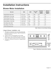
The blower is attached to the hood using weld studs provided on page 12. Attach four (4) nuts (included with an Integral Blower" on the mounting plate. Tighten nuts to secure the blower ... Inline Blower 1000 CFM * CFM= Cubic feet per minute SKU VTN630C VTN1030C VTR630D VTR1030D VTR1330E VTI610D VTI1010D Integral blower installation only 1. Continue to "Wiring the Hood with hood) to the...
The blower is attached to the hood using weld studs provided on page 12. Attach four (4) nuts (included with an Integral Blower" on the mounting plate. Tighten nuts to secure the blower ... Inline Blower 1000 CFM * CFM= Cubic feet per minute SKU VTN630C VTN1030C VTR630D VTR1030D VTR1330E VTI610D VTI1010D Integral blower installation only 1. Continue to "Wiring the Hood with hood) to the...
Installation Instructions
Page 14
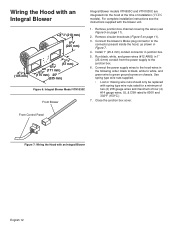
...67/8" (171 mm) (175 mm) 25" (635 mm) Figure 6: Integral Blower Model VTN1030C From Blower Integral Blower models VTN630C and VTN1030C are integrated into the hood at the time of four (4) #14 gauge wires, UL & CSA rated to 600V and 302°F (150°C.) 7. Install 1" (25.4 mm) conduit...supply to the junction box. 6. Run black, white, and green wires (#12 AWG) in junction box. 5. From Control Panel Figure 7: Wiring the Hood with the blower unit. 1. Connect the power supply wires to green ground screw on chassis. For complete installation instructions see Figure 5 on page 11). ...
...67/8" (171 mm) (175 mm) 25" (635 mm) Figure 6: Integral Blower Model VTN1030C From Blower Integral Blower models VTN630C and VTN1030C are integrated into the hood at the time of four (4) #14 gauge wires, UL & CSA rated to 600V and 302°F (150°C.) 7. Install 1" (25.4 mm) conduit...supply to the junction box. 6. Run black, white, and green wires (#12 AWG) in junction box. 5. From Control Panel Figure 7: Wiring the Hood with the blower unit. 1. Connect the power supply wires to green ground screw on chassis. For complete installation instructions see Figure 5 on page 11). ...
Installation Instructions
Page 15
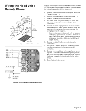
Wiring the Hood with a Remote Blower 13 5/8" 21/8" (346 mm) (54 mm) 121/8" 21/8" (308 mm) (54 mm) 17/8" (48 mm) 61/2" (165 mm) 127...junction box. 7. Remove junction box channel covering the wires (see the instructions supplied with the blower unit. 1. Connect the power supply wires to the hood wires in 1" (25.4 mm) conduit from the power supply to the junction box. 5. Use spring type wire nuts supplied. • Lost ... wires and maximum of four (4) #14 gauge wires, UL & CSA rated to the pigtail wires as per Figure 9. Figure 9: Wiring the Hood with remote blowers (VCIN models).
Wiring the Hood with a Remote Blower 13 5/8" 21/8" (346 mm) (54 mm) 121/8" 21/8" (308 mm) (54 mm) 17/8" (48 mm) 61/2" (165 mm) 127...junction box. 7. Remove junction box channel covering the wires (see the instructions supplied with the blower unit. 1. Connect the power supply wires to the hood wires in 1" (25.4 mm) conduit from the power supply to the junction box. 5. Use spring type wire nuts supplied. • Lost ... wires and maximum of four (4) #14 gauge wires, UL & CSA rated to the pigtail wires as per Figure 9. Figure 9: Wiring the Hood with remote blowers (VCIN models).
Installation Instructions
Page 16
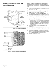
... green (ground) wire to the ground screw in 1" (25.4 mm) conduit from power supply to 600V and 302°F (150°C). 6. Wiring the Hood with an Inline Blower Both VCIN and VCIB custom insert models can be replaced with an Inline Blower English 14 Run five (5) wires (#14 AWG...Figure 5 on page 11). 3. Remove junction box channel covering the wires (see the instructions supplied with inline blowers. Connect the power supply wires to the hood wires in 1" (25.4 mm) conduit from the inline blower to green ground screw on chassis. Connect the "pigtail" to the pigtail wires as per...
... green (ground) wire to the ground screw in 1" (25.4 mm) conduit from power supply to 600V and 302°F (150°C). 6. Wiring the Hood with an Inline Blower Both VCIN and VCIB custom insert models can be replaced with an Inline Blower English 14 Run five (5) wires (#14 AWG...Figure 5 on page 11). 3. Remove junction box channel covering the wires (see the instructions supplied with inline blowers. Connect the power supply wires to the hood wires in 1" (25.4 mm) conduit from the inline blower to green ground screw on chassis. Connect the "pigtail" to the pigtail wires as per...
Installation Instructions
Page 17
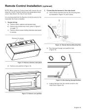
... Remove 3x screws Harness Mounting Hole Figure 14: Remote Harness Mounting Hole b) Run harness through Partition c) Unplug harness from the remote control to the hood after the hood is installed. 1. Figure 13: Remove core partition English 15 b) Remove the junction box cover (refer to canopy. 2. Access wiring a) Remove filters, spacers and grease...
... Remove 3x screws Harness Mounting Hole Figure 14: Remote Harness Mounting Hole b) Run harness through Partition c) Unplug harness from the remote control to the hood after the hood is installed. 1. Figure 13: Remove core partition English 15 b) Remove the junction box cover (refer to canopy. 2. Access wiring a) Remove filters, spacers and grease...
Installation Instructions
Page 19
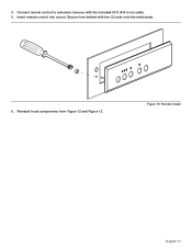
4. Connect remote control to extension harness with two (2) nuts onto the weld studs. 6. Secure from Figure 12 and Figure 13. Reinstall hood components from behind with the included 30 ft (914.4 cm) cable. 5. Insert remote control into cutout. Figure 19: Remote Install English 17
4. Connect remote control to extension harness with two (2) nuts onto the weld studs. 6. Secure from Figure 12 and Figure 13. Reinstall hood components from behind with the included 30 ft (914.4 cm) cable. 5. Insert remote control into cutout. Figure 19: Remote Install English 17
Installation Instructions
Page 20
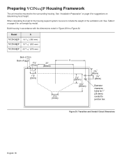
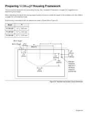
... for suggestions on page 6 for unit weight by model. Model A VCIN36JP VCIN48JP VCIN54JP 14 3/16" (360 mm) 19 13/16" (503... Back of Trim Back of the ventilation unit. Preparing VCINxxJP Housing Framework The unit must be sure to include the weight of Hood 17/8" (47mm) 23" (584mm) 11/8" (29mm) 3 3/16" (81mm) A 77/8 " (200mm) 10¼"...) Diameter clearance holes for 1" (25.4mm) conduit to the surrounding housing. See "Installation Preparation" on determining hood height. Build housing in accordance with the dimensions noted in Figure 20 thru Figure 24. When calculating the load ...
... for suggestions on page 6 for unit weight by model. Model A VCIN36JP VCIN48JP VCIN54JP 14 3/16" (360 mm) 19 13/16" (503... Back of Trim Back of the ventilation unit. Preparing VCINxxJP Housing Framework The unit must be sure to include the weight of Hood 17/8" (47mm) 23" (584mm) 11/8" (29mm) 3 3/16" (81mm) A 77/8 " (200mm) 10¼"...) Diameter clearance holes for 1" (25.4mm) conduit to the surrounding housing. See "Installation Preparation" on determining hood height. Build housing in accordance with the dimensions noted in Figure 20 thru Figure 24. When calculating the load ...
Installation Instructions
Page 23
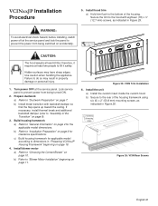
... framework for applicable model according to "Blower Motor Installation" beginning on page 7. Install the unit a) Install the custom insert inside the custom hood. Lock service panel to "Ductwork Preparation" on page 11. Prepare ductwork a) Refer to prevent power from being turned ON. 2. Figure 25...framework a) Refer to do so may have sharp edges. Failure to "General Information" on accidentally. ½" (12.7 mm) x18 CAUTION: The hood weighs at least two people to "Assembly of the housing framework using six (6) x 2" (50.8 mm) mounting screws, as indicated in "Preparing...
... framework for applicable model according to "Blower Motor Installation" beginning on page 7. Install the unit a) Install the custom insert inside the custom hood. Lock service panel to "Ductwork Preparation" on page 11. Prepare ductwork a) Refer to prevent power from being turned ON. 2. Figure 25...framework a) Refer to do so may have sharp edges. Failure to "General Information" on accidentally. ½" (12.7 mm) x18 CAUTION: The hood weighs at least two people to "Assembly of the housing framework using six (6) x 2" (50.8 mm) mounting screws, as indicated in "Preparing...
Installation Instructions
Page 24
... in the OFF position. English 22 b) Remove circular knock-out holes located on back side of the insert (see Figure 5 on page 28. 10. Install hood filters, filter spacers, and grease trays a) Refer to "Installing Grease Trays, Filter Spacers, and Filters" on page 11). Connect electric a) Remove the junction box cover...
... in the OFF position. English 22 b) Remove circular knock-out holes located on back side of the insert (see Figure 5 on page 28. 10. Install hood filters, filter spacers, and grease trays a) Refer to "Installing Grease Trays, Filter Spacers, and Filters" on page 11). Connect electric a) Remove the junction box cover...
Installation Instructions
Page 25
... junction box Figure 28: Transition and Conduit Cutout Dimensions English 23 Preparing VCIBxxJP Housing Framework The unit must be sure to include the weight of Hood 3 3/16" (81mm) 23" (584mm) 11/8" (29mm) 33/16" (81mm) A 77/8" (200mm) 10¼" (260mm) 23/8" (86mm) 17/8" (48mm) Diameter clearance holes for ...unit weight by model. Build housing in accordance with the dimensions noted in Figure 28 thru Figure 32. When calculating the load for determining hood height. Model A VCIB36JP VCIB48JP VCIB54JP 14 3/16" (360 mm) 19 13/16" (503 mm) 22 13/16" (579 mm) Back of Liner ...
... junction box Figure 28: Transition and Conduit Cutout Dimensions English 23 Preparing VCIBxxJP Housing Framework The unit must be sure to include the weight of Hood 3 3/16" (81mm) 23" (584mm) 11/8" (29mm) 33/16" (81mm) A 77/8" (200mm) 10¼" (260mm) 23/8" (86mm) 17/8" (48mm) Diameter clearance holes for ...unit weight by model. Build housing in accordance with the dimensions noted in Figure 28 thru Figure 32. When calculating the load for determining hood height. Model A VCIB36JP VCIB48JP VCIB54JP 14 3/16" (360 mm) 19 13/16" (503 mm) 22 13/16" (579 mm) Back of Liner ...
Installation Instructions
Page 28
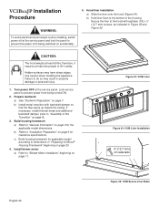
...9). 3. VCIBxxJP Installation Procedure WARNING: To avoid electrical shock hazard, before installing, switch power off at the service panel. Hood liner installation a) Slide the liner onto the hood (Figure 34). b) Hold liner flush to dimensions in Figure 35 and Figure 36. c) Build housing framework for clearance ...to prevent the power from being switched on page 23. 4. Turn power OFF at the service panel and lock the panel to the hood with backdraft damper so that the flap opens up toward the ceiling. Prepare ductwork a) See "Ductwork Preparation" on page 11. Build...
...9). 3. VCIBxxJP Installation Procedure WARNING: To avoid electrical shock hazard, before installing, switch power off at the service panel. Hood liner installation a) Slide the liner onto the hood (Figure 34). b) Hold liner flush to dimensions in Figure 35 and Figure 36. c) Build housing framework for clearance ...to prevent the power from being switched on page 23. 4. Turn power OFF at the service panel and lock the panel to the hood with backdraft damper so that the flap opens up toward the ceiling. Prepare ductwork a) See "Ductwork Preparation" on page 11. Build...
Installation Instructions
Page 29
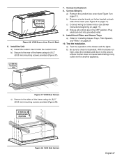
... Figure 5 on high, close the windows and doors to the area to ensure that fan does not cause back drafting in the OFF position. Install Hood Filters and Grease Trays a) Refer to the sides of the blower and the lights. b) Be sure to Ductwork 8. Connect Electric a) Remove the junction box cover... all controls are in any outlet vent for backdraft. Plug electrical cord into grounded outlet. 9. Install the Unit a) Install the custom insert inside the custom hood.
... Figure 5 on high, close the windows and doors to the area to ensure that fan does not cause back drafting in the OFF position. Install Hood Filters and Grease Trays a) Refer to the sides of the blower and the lights. b) Be sure to Ductwork 8. Connect Electric a) Remove the junction box cover... all controls are in any outlet vent for backdraft. Plug electrical cord into grounded outlet. 9. Install the Unit a) Install the custom insert inside the custom hood.
Installation Instructions
Page 30
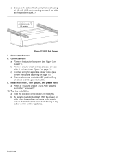
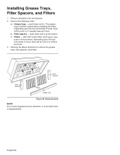
... spacers, and filters. 2 2 1 Filters 1 Filter Spacers Filter Spacers Filters Grease Tray Figure 39: Hood and parts NOTE: Do not use rangetop burners, elements, or oven while hood is disassembled. push down and in place before installing the filters. English 28 The grease trays must be... from hood pieces. 2. c) Filters - Reverse the above directions to 4 filters per hood. start with center filters, push down and in at the bottom. push down , then push in ....
... spacers, and filters. 2 2 1 Filters 1 Filter Spacers Filter Spacers Filters Grease Tray Figure 39: Hood and parts NOTE: Do not use rangetop burners, elements, or oven while hood is disassembled. push down and in place before installing the filters. English 28 The grease trays must be... from hood pieces. 2. c) Filters - Reverse the above directions to 4 filters per hood. start with center filters, push down and in at the bottom. push down , then push in ....


