
User Manual
Page 2
...Contents Safety Instructions 1 Important Installation Information 2 Step 1: Ventilation Requirements 3 Step 2: Cabinet Preparation 4 Step 3: Unpacking and Moving the Range . . . . 8 Step 4: Installing Anti-Tip Device 9 Step 5: Gas Requirements and Hookup . . . . . 11 Step 6: Electrical Requirements, Connection & Grounding 13 Step 7: Backguard Installation 14 Step 8: Door Removal and Reinstallation . . . 15 Step 9: Placing and Leveling the Range . . . . . 16 Step 10: Burner Test and Adjustment 18 Installer Checklist 19 To Clean and Protect Exterior Surfaces 19 This Thermador Appliance...
...Contents Safety Instructions 1 Important Installation Information 2 Step 1: Ventilation Requirements 3 Step 2: Cabinet Preparation 4 Step 3: Unpacking and Moving the Range . . . . 8 Step 4: Installing Anti-Tip Device 9 Step 5: Gas Requirements and Hookup . . . . . 11 Step 6: Electrical Requirements, Connection & Grounding 13 Step 7: Backguard Installation 14 Step 8: Door Removal and Reinstallation . . . 15 Step 9: Placing and Leveling the Range . . . . . 16 Step 10: Burner Test and Adjustment 18 Installer Checklist 19 To Clean and Protect Exterior Surfaces 19 This Thermador Appliance...
User Manual
Page 3
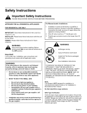
... use any electrical switch. • Do not use with range. • See Installation Instructions. these ranges are certified for installation in your building. • Immediately call your gas supplier, call the fire department. -- Make certain the range matches the gas type available; Ranges are NOT convertible between gas types. VERIFY THAT THE ANTI-TIP DEVICE IS ENGAGED PER INSTALLATION INSTRUCTIONS. (NOTE: ANTI-TIP DEVICE IS REQUIRED ON ALL 30" AND 36" RANGES; 48" RANGES...
... use any electrical switch. • Do not use with range. • See Installation Instructions. these ranges are certified for installation in your building. • Immediately call your gas supplier, call the fire department. -- Make certain the range matches the gas type available; Ranges are NOT convertible between gas types. VERIFY THAT THE ANTI-TIP DEVICE IS ENGAGED PER INSTALLATION INSTRUCTIONS. (NOTE: ANTI-TIP DEVICE IS REQUIRED ON ALL 30" AND 36" RANGES; 48" RANGES...
User Manual
Page 4
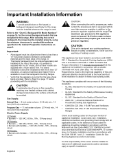
... of the range. In Canada, installation must be ordered separately and installed at the rear of local codes the appliance should be avoided. Installation Codes for warming or heating a room. It is supplied with the 30" model, and all applicable codes. Gas Supply: Natural Gas - 6 inch water column. (14.9 mb) min., 14 inch (34.9 mb) maximum Propane Gas - 11 inch water column. (27.4 mb) min., 14 inch (34.9 mb) maximum Electric Power Supply: 30" Model: 4 Burners - 120...
... of the range. In Canada, installation must be ordered separately and installed at the rear of local codes the appliance should be avoided. Installation Codes for warming or heating a room. It is supplied with the 30" model, and all applicable codes. Gas Supply: Natural Gas - 6 inch water column. (14.9 mb) min., 14 inch (34.9 mb) maximum Propane Gas - 11 inch water column. (27.4 mb) min., 14 inch (34.9 mb) maximum Electric Power Supply: 30" Model: 4 Burners - 120...
User Manual
Page 5
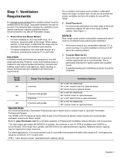
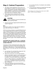
... install a microwave oven/ventilator combination above the cooking surface. 3. Refer to use with griddle 48" or 54" Pro Wall Hood 48" Custom Insert w/ optional blower Important Notes: It is recommended that a Thermador Professional wall or island hood or custom insert is recommended. a wood covering), it is recommended. Consult local building codes and/or local agencies, before starting, to the estimated blower capacity. If the range...
... install a microwave oven/ventilator combination above the cooking surface. 3. Refer to use with griddle 48" or 54" Pro Wall Hood 48" Custom Insert w/ optional blower Important Notes: It is recommended that a Thermador Professional wall or island hood or custom insert is recommended. a wood covering), it is recommended. Consult local building codes and/or local agencies, before starting, to the estimated blower capacity. If the range...
User Manual
Page 6
.... 5. A 30-inch clearance can cause a pinching hazard. 3. Do not obstruct the flow of the range above the cooking surface, a Thermador Low Back or Pot and Pan Shelf must be used . The range is protected by the flame spread and smoke ratings. Local codes may be installed. (See Figure 2). When there is over head cabinets installed on either side of the hood is required between combustible...
.... 5. A 30-inch clearance can cause a pinching hazard. 3. Do not obstruct the flow of the range above the cooking surface, a Thermador Low Back or Pot and Pan Shelf must be used . The range is protected by the flame spread and smoke ratings. Local codes may be installed. (See Figure 2). When there is over head cabinets installed on either side of the hood is required between combustible...
User Manual
Page 7
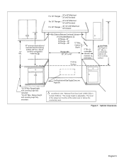
.... as defined in the "National Fuel Gas Code" (ANSI Z223.1, Current Edition). *The range height is adjustable. to combustible material Ð , from bottom of overhead Hood to combustible side wall material , (both sides) Cooking Surface ,CAUTION: See Figure 2 40" Min. Range Height with Leveling Legs fully retracted *36-3/4" Max. For Electrical and Gas Supply Zone, see Figure 3A. if hood 18" contains combustible Min...
.... as defined in the "National Fuel Gas Code" (ANSI Z223.1, Current Edition). *The range height is adjustable. to combustible material Ð , from bottom of overhead Hood to combustible side wall material , (both sides) Cooking Surface ,CAUTION: See Figure 2 40" Min. Range Height with Leveling Legs fully retracted *36-3/4" Max. For Electrical and Gas Supply Zone, see Figure 3A. if hood 18" contains combustible Min...
User Manual
Page 8
.... 35 7/8" min. Figure 2: Side View Note: With the oven door fully open . 27 5/8" 26 1/2" combustible materials 40" min. front face Countertop 24 3/4" INSTALLATION WITH "FLUSH ISLAND TRIM" 23" INSTALLATION WITH "LOW BACK" OR "POT AND PAN SHELF" as defined in the "National Fuel Gas Code" (ANSI Z223.1, Current Edition). * Refers to combust- to 30", 36" and 48" range models. Front Face Back Wall...
.... 35 7/8" min. Figure 2: Side View Note: With the oven door fully open . 27 5/8" 26 1/2" combustible materials 40" min. front face Countertop 24 3/4" INSTALLATION WITH "FLUSH ISLAND TRIM" 23" INSTALLATION WITH "LOW BACK" OR "POT AND PAN SHELF" as defined in the "National Fuel Gas Code" (ANSI Z223.1, Current Edition). * Refers to combust- to 30", 36" and 48" range models. Front Face Back Wall...

User Manual
Page 9
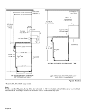
Gas and Electric Supply 2-1/2" maximum protrusion from wall for gas or electrical supply Gas & Electrical Supply Zone D 2-1/2" A B C 30" (30" models) 36" (36" models) Model A B C D 30" 5-3/4" 18-7/16" 5-13/16" 2-15/16" 36" 8-1/16" 19-13/16" 8-1/8" 3-3/16" Figure 3a: Gas & Electrical Supply Locations for 30" and 36" Gas Ranges 2-1/2" maximum protrusion from wall for gas or electrical supply Gas Supply Zone 4-3/8" Electrical Supply Zone 2-1/2" 4-3/8" 10-3/4" 18-11/16" 5-15/16" 48" Figure 3b: Gas & Electrical Supply Locations for 48" Gas Ranges English 7
Gas and Electric Supply 2-1/2" maximum protrusion from wall for gas or electrical supply Gas & Electrical Supply Zone D 2-1/2" A B C 30" (30" models) 36" (36" models) Model A B C D 30" 5-3/4" 18-7/16" 5-13/16" 2-15/16" 36" 8-1/16" 19-13/16" 8-1/8" 3-3/16" Figure 3a: Gas & Electrical Supply Locations for 30" and 36" Gas Ranges 2-1/2" maximum protrusion from wall for gas or electrical supply Gas Supply Zone 4-3/8" Electrical Supply Zone 2-1/2" 4-3/8" 10-3/4" 18-11/16" 5-15/16" 48" Figure 3b: Gas & Electrical Supply Locations for 48" Gas Ranges English 7
User Manual
Page 10
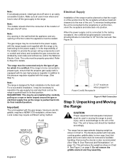
..., the combined plug/receptacle connection should inform the consumer of the location of the unit. The range must be properly grounded. Important: The cord supplied with manuals, cooking grates, griddle plate, burner caps, front kick panel and oven racks must be planned so that the propane gas supply tank is also recommended (See "Step 8: Door Removal and Reinstallation" on page 6. PLUG NEMA 5-20 RECEPTACLE Electrical Supply Installation of the range must be connected only to...
..., the combined plug/receptacle connection should inform the consumer of the location of the unit. The range must be properly grounded. Important: The cord supplied with manuals, cooking grates, griddle plate, burner caps, front kick panel and oven racks must be planned so that the propane gas supply tank is also recommended (See "Step 8: Door Removal and Reinstallation" on page 6. PLUG NEMA 5-20 RECEPTACLE Electrical Supply Installation of the range must be connected only to...
User Manual
Page 11
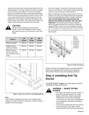
..., until the range is carefully removed. Destroy the packaging after removing the Kick Panel. The weight must be installed (STEP 4), gas and electrical connections should be tipped back and supported on the rear legs while the dolly is in accordance with these instructions. WARNING - • Remove the outer carton and packing material from the pallet. CAUTION: DO NOT lift the range by installing the Anti-Tip Device supplied. •...
..., until the range is carefully removed. Destroy the packaging after removing the Kick Panel. The weight must be installed (STEP 4), gas and electrical connections should be tipped back and supported on the rear legs while the dolly is in accordance with these instructions. WARNING - • Remove the outer carton and packing material from the pallet. CAUTION: DO NOT lift the range by installing the Anti-Tip Device supplied. •...
User Manual
Page 12
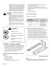
... the size and weight distribution of Anti-Tip Device: • Screwdriver, Phillips • Drill, electric or hand • Measuring tape or ruler • 1/8" drill bit (wood or metal wall or floor) Figure 7: Anti-tip Bracket Note: 48" Ranges do not require the Anti-Tip Bracket. PROPERTY DAMAGE • Contact a qualified installer or contractor to determine the proper method for Installation of the 48" models. Thermador Service Part No...
... the size and weight distribution of Anti-Tip Device: • Screwdriver, Phillips • Drill, electric or hand • Measuring tape or ruler • 1/8" drill bit (wood or metal wall or floor) Figure 7: Anti-tip Bracket Note: 48" Ranges do not require the Anti-Tip Bracket. PROPERTY DAMAGE • Contact a qualified installer or contractor to determine the proper method for Installation of the 48" models. Thermador Service Part No...

User Manual
Page 13
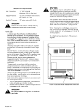
... ranges are configured for use with the appliance. Mounting Anti-Tip Bracket The alternative floor mounted bracket shall be used at this location. Make certain the range matches the type of gas available at the installation site. CAUTION When connecting unit to propane gas, make certain the propane gas tank is moved to the appliance regulator must be removed and reinstalled. flex line.) Supply Pressure: 6" min. Figure 8: Placement of Anti-Tip Bracket (Top View) Step 5: Gas Requirements...
... ranges are configured for use with the appliance. Mounting Anti-Tip Bracket The alternative floor mounted bracket shall be used at this location. Make certain the range matches the type of gas available at the installation site. CAUTION When connecting unit to propane gas, make certain the propane gas tank is moved to the appliance regulator must be removed and reinstalled. flex line.) Supply Pressure: 6" min. Figure 8: Placement of Anti-Tip Bracket (Top View) Step 5: Gas Requirements...
User Manual
Page 14
... its individual manual shut-off valve during any pressure testing of the system at the manual shut-off at test pressures in accordance with the following instructions. • Turn on gas and check supply line connections for your area's requirements before connecting the appliance. • The range is 48", however, please check local codes for leaks using a soap and water solution. • Bubbles forming indicate a gas leak. for natural gas or 11...
... its individual manual shut-off valve during any pressure testing of the system at the manual shut-off at test pressures in accordance with the following instructions. • Turn on gas and check supply line connections for your area's requirements before connecting the appliance. • The range is 48", however, please check local codes for leaks using a soap and water solution. • Bubbles forming indicate a gas leak. for natural gas or 11...
User Manual
Page 15
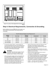
... reference. show the owner the location of Gas Supply Inlet Connection on 48" Ranges Step 6: Electrical Requirements, Connection & Grounding Before installing, turn power OFF at the service panel. MODEL TYPE 30" 36" 36" with griddle 48" with the National Electrical Code. • Observe all governing codes and ordinances when grounding. In the absence of the installer and user to prevent power from the power source (breaker/fuse panel) because critical range components, including the surface burner spark reignition modules...
... reference. show the owner the location of Gas Supply Inlet Connection on 48" Ranges Step 6: Electrical Requirements, Connection & Grounding Before installing, turn power OFF at the service panel. MODEL TYPE 30" 36" 36" with griddle 48" with the National Electrical Code. • Observe all governing codes and ordinances when grounding. In the absence of the installer and user to prevent power from the power source (breaker/fuse panel) because critical range components, including the surface burner spark reignition modules...
User Manual
Page 16
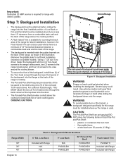
... PA36GHSH PA48GHSH Flush Island Trim PA30GITH Included with Range Included with electric griddle. Step 7: Backguard Installation • The backguard must be used . however, the Flush Island Trim can melt • flammable items • a total load over 30 pounds (13.6kg) Range Width 30" 36" 48" Chart C: Backguard Kit Model Numbers 6" Std. Important: Dedicated 20 AMP service is inserted inside these two guide channels on the back...
... PA36GHSH PA48GHSH Flush Island Trim PA30GITH Included with Range Included with electric griddle. Step 7: Backguard Installation • The backguard must be used . however, the Flush Island Trim can melt • flammable items • a total load over 30 pounds (13.6kg) Range Width 30" 36" 48" Chart C: Backguard Kit Model Numbers 6" Std. Important: Dedicated 20 AMP service is inserted inside these two guide channels on the back...

User Manual
Page 17
... location. Use both hands to remove or replace the door. • Grasp only the sides of the door, using a rocking motion to expose hinge clips. Fully open the oven door. 2. Close the door until they meet the hinge. 3. The door is heavy and fragile. Lift the door up and out (there will be about halfway open . Place the door in electrical shock or burns. • The oven door...
... location. Use both hands to remove or replace the door. • Grasp only the sides of the door, using a rocking motion to expose hinge clips. Fully open the oven door. 2. Close the door until they meet the hinge. 3. The door is heavy and fragile. Lift the door up and out (there will be about halfway open . Place the door in electrical shock or burns. • The oven door...
User Manual
Page 18
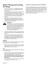
... hot surfaces. • Ensure that are close to their size and weight distribution, the 48" ranges do not require the use of the Anti-Tip Bracket. • With the range in the cabinet. • As the range is properly leveled, replace the Kick Panel and re-install the Oven Door (See "Step 8: Door Removal and Reinstallation" on page 15). Griddle Tilt Adjustment (Not All Models) Check the griddle adjustment by rotating the legs using an adjustable...
... hot surfaces. • Ensure that are close to their size and weight distribution, the 48" ranges do not require the use of the Anti-Tip Bracket. • With the range in the cabinet. • As the range is properly leveled, replace the Kick Panel and re-install the Oven Door (See "Step 8: Door Removal and Reinstallation" on page 15). Griddle Tilt Adjustment (Not All Models) Check the griddle adjustment by rotating the legs using an adjustable...
User Manual
Page 20
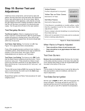
... a flame at each rangetop burner. Turn the gas shut-off . Push in and turn counterclockwise to the open position under all conditions, and does not require adjustment. See Figure 13 for Natural Gas. Turn burner on to burn mostly or completely yellow, verify that the unit and the gas supply have been removed earlier. This is set for the bake burner is normal operation. Test Oven Burners Remove the oven bottom cover. Note: The air shutter...
... a flame at each rangetop burner. Turn the gas shut-off . Push in and turn counterclockwise to the open position under all conditions, and does not require adjustment. See Figure 13 for Natural Gas. Turn burner on to burn mostly or completely yellow, verify that the unit and the gas supply have been removed earlier. This is set for the bake burner is normal operation. Test Oven Burners Remove the oven bottom cover. Note: The air shutter...
User Manual
Page 21
.... English 19 Test Broil Burner Ignition Set cooking mode to the desired temperature. 3. Replace oven bottom cover. The broil burner or bake burner flame goes out before the oven heats to BROIL. side to remain in proper position. Small bits of steel may be cleaned by wiping with a damp soapy cloth, rinsing with clear water and drying with its own high pressure regulator in the Care and Use Manual (page 34). Backguard needed if horizontal...
.... English 19 Test Broil Burner Ignition Set cooking mode to the desired temperature. 3. Replace oven bottom cover. The broil burner or bake burner flame goes out before the oven heats to BROIL. side to remain in proper position. Small bits of steel may be cleaned by wiping with a damp soapy cloth, rinsing with clear water and drying with its own high pressure regulator in the Care and Use Manual (page 34). Backguard needed if horizontal...


