
User's Guide
Page 4
... Server Statistics...10-14 IGMP SNOOPING ...10-14 IGMP Snooping Clear Statistics ...10-14 IGMP Snooping V1/V2 Statistics ...10-15 IP ...10-15 ARP Cache...10-15 ICMP Statistics ...10-15 RMON ...10-16 MAC ADDRESS TABLE ...10-16 SNMP ...10-......12-2 SYSTEM LOCATION ...12-2 SYSTEM WEB-TIMEOUT...12-2 SYSTEM CLI-TIMEOUT ...12-3 DEFAULT IP ADDRESS ...12-3 DEFAULT IP ADDRESS ALLOCATION PROTOCOL 12-4 DEFAULT MODE ...12-5 DEFAULT RESTORE ...12-5 DEFAULT RESTORE-FILE...12-6 DEFAULT VLAN ID...12-6 SET IP HTTP ...12-7 IP HTTP PORT...12-7 SHOW SYSTEM INFORMATION...12-7 SHOW NVRAM ...12-8 SHOW HTTP SERVER...
... Server Statistics...10-14 IGMP SNOOPING ...10-14 IGMP Snooping Clear Statistics ...10-14 IGMP Snooping V1/V2 Statistics ...10-15 IP ...10-15 ARP Cache...10-15 ICMP Statistics ...10-15 RMON ...10-16 MAC ADDRESS TABLE ...10-16 SNMP ...10-......12-2 SYSTEM LOCATION ...12-2 SYSTEM WEB-TIMEOUT...12-2 SYSTEM CLI-TIMEOUT ...12-3 DEFAULT IP ADDRESS ...12-3 DEFAULT IP ADDRESS ALLOCATION PROTOCOL 12-4 DEFAULT MODE ...12-5 DEFAULT RESTORE ...12-5 DEFAULT RESTORE-FILE...12-6 DEFAULT VLAN ID...12-6 SET IP HTTP ...12-7 IP HTTP PORT...12-7 SHOW SYSTEM INFORMATION...12-7 SHOW NVRAM ...12-8 SHOW HTTP SERVER...

User's Guide
Page 8
... RE-AUTHENTICATE ...31-1 DOT1X SYSTEM-AUTH-CONTROL ...31-2 AAA AUTHENTICATION DOT1X DEFAULT ...31-2 DOT1X LOCAL-DATABASE...31-2 RADIUS-SERVER HOST...31-3 DOT1X CONTROL-DIRECTION ...31-4 DOT1X DEFAULT...31-5 DOT1X MAX-REQ...31-5 DOT1X MAX-START...31-6 DOT1X PORT-CONTROL...IP IGMP SNOOPING REPORT-FORWARD ...32-4 IP IGMP SNOOPING REPORT-SUPPRESSION-INTERVAL 32-5 IP IGMP SNOOPING RETRY-COUNT ...32-5 IP IGMP SNOOPING SEND-QUERY ...32-6 IP IGMP SNOOPING FAST-LEAVE ...32-6 IP IGMP SNOOPING QUERIER ...32-7 SHUTDOWN SNOOPING ...32-7 DEBUG IP IGMP SNOOPING ...32-8 SHOW IP IGMP SNOOPING ...32-9 SHOW IP...
... RE-AUTHENTICATE ...31-1 DOT1X SYSTEM-AUTH-CONTROL ...31-2 AAA AUTHENTICATION DOT1X DEFAULT ...31-2 DOT1X LOCAL-DATABASE...31-2 RADIUS-SERVER HOST...31-3 DOT1X CONTROL-DIRECTION ...31-4 DOT1X DEFAULT...31-5 DOT1X MAX-REQ...31-5 DOT1X MAX-START...31-6 DOT1X PORT-CONTROL...IP IGMP SNOOPING REPORT-FORWARD ...32-4 IP IGMP SNOOPING REPORT-SUPPRESSION-INTERVAL 32-5 IP IGMP SNOOPING RETRY-COUNT ...32-5 IP IGMP SNOOPING SEND-QUERY ...32-6 IP IGMP SNOOPING FAST-LEAVE ...32-6 IP IGMP SNOOPING QUERIER ...32-7 SHUTDOWN SNOOPING ...32-7 DEBUG IP IGMP SNOOPING ...32-8 SHOW IP IGMP SNOOPING ...32-9 SHOW IP...

User's Guide
Page 10
COSQ SCHEDULING ALGORITHM ...40-2 SWITCHPORT PRIORITY DEFAULT ...40-3 SHOW VLAN TRAFFIC-CLASSES ...40-3 SHOW VLAN PORT CONFIG ...40-4 SHOW DSCP...40-5 SHOW COSQ ALGORITHM ...40-5 CHAPTER 41 RMON COMMAND...41-1 RMON COMMAND ... ...41-2 RMON COLLECTION HISTORY...41-3 RMON COLLECTION STATS ...41-3 SHOW RMON...41-4 CHAPTER 42 STATISTICS COMMAND 42-1 STATISTICS COMMAND LIST...42-1 CLEAR INTERFACES...42-1 SHOW IP TRAFFIC ...42-1 CHAPTER 43 SYSTEM OPERATION COMMAND 43-1 SYSTEM OPERATION COMMAND LIST...43-1 WATCHDOG ...43-1 COPY ...43-1 PING ...43-2 HELP ...43-3 CLEAR SCREEN...43-3 LOCK...
COSQ SCHEDULING ALGORITHM ...40-2 SWITCHPORT PRIORITY DEFAULT ...40-3 SHOW VLAN TRAFFIC-CLASSES ...40-3 SHOW VLAN PORT CONFIG ...40-4 SHOW DSCP...40-5 SHOW COSQ ALGORITHM ...40-5 CHAPTER 41 RMON COMMAND...41-1 RMON COMMAND ... ...41-2 RMON COLLECTION HISTORY...41-3 RMON COLLECTION STATS ...41-3 SHOW RMON...41-4 CHAPTER 42 STATISTICS COMMAND 42-1 STATISTICS COMMAND LIST...42-1 CLEAR INTERFACES...42-1 SHOW IP TRAFFIC ...42-1 CHAPTER 43 SYSTEM OPERATION COMMAND 43-1 SYSTEM OPERATION COMMAND LIST...43-1 WATCHDOG ...43-1 COPY ...43-1 PING ...43-2 HELP ...43-3 CLEAR SCREEN...43-3 LOCK...

User's Guide
Page 16
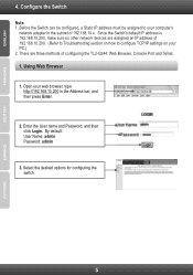
...D) Firefox 1.5/2.0 or higher Connecting to login and configure the switch via an Ethernet connection, the PC must have an IP address of 192.168.10.x (where x is a number between 1 ~ 254), and a subnet mask of 255.... 4-1 Figure 6 - Enter the IP address 192.168.10.200 in the same subnet as the switch. Open the web browser and enter 192.168.10.200 (the factory-default IP address) in the address bar. ...Then press . For example, if the switch has an IP address of 192.168.10.200, the PC should have an IP address in the...
...D) Firefox 1.5/2.0 or higher Connecting to login and configure the switch via an Ethernet connection, the PC must have an IP address of 192.168.10.x (where x is a number between 1 ~ 254), and a subnet mask of 255.... 4-1 Figure 6 - Enter the IP address 192.168.10.200 in the same subnet as the switch. Open the web browser and enter 192.168.10.200 (the factory-default IP address) in the address bar. ...Then press . For example, if the switch has an IP address of 192.168.10.200, the PC should have an IP address in the...

User's Guide
Page 17
Device Status Function Tree 4-2 Figure 8 - Web User Interface Main Configuration Screen The three main areas are : User Name Password Privilege admin admin 15 guest guest123 1 After login successfully, following page will appear. Enter the IP address 192.168.10.200 in the web browser The default user name and password are the Device Status on top, the Function Tree, and the 24-Port Gigabit Layer 2 Switch w/ 4 Shared Mini-GBIC Slots Note Figure 7 -
Device Status Function Tree 4-2 Figure 8 - Web User Interface Main Configuration Screen The three main areas are : User Name Password Privilege admin admin 15 guest guest123 1 After login successfully, following page will appear. Enter the IP address 192.168.10.200 in the web browser The default user name and password are the Device Status on top, the Function Tree, and the 24-Port Gigabit Layer 2 Switch w/ 4 Shared Mini-GBIC Slots Note Figure 7 -
User's Guide
Page 21
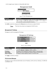
...from 1 to 4094, a range of VLAN IDs separated by a comma (,) Click ADD to edit the management IP settings. System > IP Settings Parameter IP Address Mode IP Address Subnet Mask Default Gateway Description To configure the mode that it is assigned. Click Apply to visit. 5-3 24-Port Gigabit Layer...Switch w/ 4 Shared Mini-GBIC Slots Figure 11 - IP address of the management interface. Default is Manual. You can be at least one management VLAN ID exists. IP address of management VLAN. Default is 192.168.10.254. IP Authorized Manager This page is 255.255.255.0. System ...
...from 1 to 4094, a range of VLAN IDs separated by a comma (,) Click ADD to edit the management IP settings. System > IP Settings Parameter IP Address Mode IP Address Subnet Mask Default Gateway Description To configure the mode that it is assigned. Click Apply to visit. 5-3 24-Port Gigabit Layer...Switch w/ 4 Shared Mini-GBIC Slots Figure 11 - IP address of the management interface. Default is Manual. You can be at least one management VLAN ID exists. IP address of management VLAN. Default is 192.168.10.254. IP Authorized Manager This page is 255.255.255.0. System ...

User's Guide
Page 25
.... The name of the device. The default is to configure the SNMP engine identifier of SNMP community/user that can access to submit the changes and the Reset button will clear the information. System > SNMP > Trap Manager Parameter Host IP Address SNMP version Community Name/User Name... Description The IP address of between 5 and 32 octets expressed in hexadecimal. Select and click Delete to submit the changes and ...
.... The name of the device. The default is to configure the SNMP engine identifier of SNMP community/user that can access to submit the changes and the Reset button will clear the information. System > SNMP > Trap Manager Parameter Host IP Address SNMP version Community Name/User Name... Description The IP address of between 5 and 32 octets expressed in hexadecimal. Select and click Delete to submit the changes and ...

User's Guide
Page 27
.... System > System Log Parameter Syslog Status Time Stamp Messages Buffered Size (1-200) Syslog Server IP Mail Server IP Receiver Email Address Sender Email Address Facility Logging Level Description The status of sender that receives the alert messages. Default is info. Default is Local0. The email address of syslog server function. Possible values: local0, local1...
.... System > System Log Parameter Syslog Status Time Stamp Messages Buffered Size (1-200) Syslog Server IP Mail Server IP Receiver Email Address Sender Email Address Facility Logging Level Description The status of sender that receives the alert messages. Default is info. Default is Local0. The email address of syslog server function. Possible values: local0, local1...

User's Guide
Page 28
... To enable/disable the DST function. Parameter Daylight Saving Time Status Daylight Saving Time: From (Month:Day:HH:MM) 5-10 Figure 24 - Default is 30. Specify the DST period in Seconds (30-86400) SNTP Primary Server SNTP Secondary Server Time Zone Offset (HH:MM) Year:Month:...SS Description Current system time. 24-Port Gigabit Layer 2 Switch w/ 4 Shared Mini-GBIC Slots Figure 23 - Default is from 30 to GMT. To set the secondary SNTP server IP address. Click Apply to configure the daylight saving time function of current time zone relative to 86400 seconds. To ...
... To enable/disable the DST function. Parameter Daylight Saving Time Status Daylight Saving Time: From (Month:Day:HH:MM) 5-10 Figure 24 - Default is 30. Specify the DST period in Seconds (30-86400) SNTP Primary Server SNTP Secondary Server Time Zone Offset (HH:MM) Year:Month:...SS Description Current system time. 24-Port Gigabit Layer 2 Switch w/ 4 Shared Mini-GBIC Slots Figure 23 - Default is from 30 to GMT. To set the secondary SNTP server IP address. Click Apply to configure the daylight saving time function of current time zone relative to 86400 seconds. To ...
User's Guide
Page 30
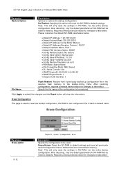
... settings in the device‟s flash memory to default value. Please reference the default NV-RAM parameters below. Default IP Address : 192.168.10.200 Default Subnet Mask: 255.255.255.0 Default IP Address Config Mode: Manual Default IP Address Allocation Protocol : DHCP Default Interface Name: Fa0/1 Default RM Interface Name: NONE Config Restore...
... settings in the device‟s flash memory to default value. Please reference the default NV-RAM parameters below. Default IP Address : 192.168.10.200 Default Subnet Mask: 255.255.255.0 Default IP Address Config Mode: Manual Default IP Address Allocation Protocol : DHCP Default Interface Name: Fa0/1 Default RM Interface Name: NONE Config Restore...
User's Guide
Page 31
... Layer 2 Switch w/ 4 Shared Mini-GBIC Slots Please reference the default NV-RAM parameters below. Default IP Address : 192.168.10.200 Default Subnet Mask: 255.255.255.0 Default IP Address Config Mode: Manual Default IP Address Allocation Protocol : DHCP Default Interface Name: Fa0/1 Default RM Interface Name: NONE Config Restore Option: No restore...
... Layer 2 Switch w/ 4 Shared Mini-GBIC Slots Please reference the default NV-RAM parameters below. Default IP Address : 192.168.10.200 Default Subnet Mask: 255.255.255.0 Default IP Address Config Mode: Manual Default IP Address Allocation Protocol : DHCP Default Interface Name: Fa0/1 Default RM Interface Name: NONE Config Restore Option: No restore...

User's Guide
Page 43
... True to enable the root guard function, False to prevent the topology change caused by this port. Figure 42 - Default 200000000 MSTP CIST Port Status To display the current MSTP CIST port status. 6-11 Default is 0-200000000. Default is to the map list of this port. MSTP VLAN Mapping This page is false... MSTP settings. Delete a VLAN from the map list of this MST instance. MSTP Port Settings This page is 128. Port ID. Specify the MST instance IP of this port. Possible value is 0-240. Specify the path cost of the port.
... True to enable the root guard function, False to prevent the topology change caused by this port. Figure 42 - Default 200000000 MSTP CIST Port Status To display the current MSTP CIST port status. 6-11 Default is 0-200000000. Default is to the map list of this port. MSTP VLAN Mapping This page is false... MSTP settings. Delete a VLAN from the map list of this MST instance. MSTP Port Settings This page is 128. Port ID. Specify the MST instance IP of this port. Possible value is 0-240. Specify the path cost of the port.

User's Guide
Page 83
...(not Windows keys). 9. Many commands require administrator-level access privileges. 13. Each Switch must firstly create user names and passwords. The Switch's default IP address is no parity. 6. This port is a male DB-9 connector, implemented as follows: 3. Set the terminal emulation software as data communication.... 8. Select the appropriate serial port (COM port 1 or COM port 2). 4. The user can change the default Switch IP address to 8 data bits, 1 stop bit, and no default user name and password for communication with the logout 24-Port Gigabit Layer 2 Switch w/ 4 Shared Mini-GBIC ...
...(not Windows keys). 9. Many commands require administrator-level access privileges. 13. Each Switch must firstly create user names and passwords. The Switch's default IP address is no parity. 6. This port is a male DB-9 connector, implemented as follows: 3. Set the terminal emulation software as data communication.... 8. Select the appropriate serial port (COM port 1 or COM port 2). 4. The user can change the default Switch IP address to 8 data bits, 1 stop bit, and no default user name and password for communication with the logout 24-Port Gigabit Layer 2 Switch w/ 4 Shared Mini-GBIC ...

User's Guide
Page 87
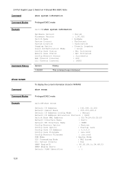
...trendnet Command History Version 1.00.001 History This command was introduced. 12-1 24-Port Gigabit Layer 2 Switch w/ 4 Shared Mini-GBIC Slots Chapter 12 System Information Command System Information Command List system name system contact system location system web-timeout system cli-timeout default ip address default ip... address allocation protocol default mode default restore default restore-file default vlan id set ip http ip http...
...trendnet Command History Version 1.00.001 History This command was introduced. 12-1 24-Port Gigabit Layer 2 Switch w/ 4 Shared Mini-GBIC Slots Chapter 12 System Information Command System Information Command List system name system contact system location system web-timeout system cli-timeout default ip address default ip... address allocation protocol default mode default restore default restore-file default vlan id set ip http ip http...

User's Guide
Page 89
... of time the device times out when no user activity occurs on the CLI interface. default ip address To configure the default IP interface. 12-3 Command system cli-timeout Syntax Description Default Settings 1-18000 seconds The cli interface logs out the current user when no user activity ... History This command was introduced. 24-Port Gigabit Layer 2 Switch w/ 4 Shared Mini-GBIC Slots Command system web-timeout Syntax Description Default Settings 180-3600 seconds The web interface logs out the current user when no user activity input for 1-18000 seconds. 1800 seconds Command...
... of time the device times out when no user activity occurs on the CLI interface. default ip address To configure the default IP interface. 12-3 Command system cli-timeout Syntax Description Default Settings 1-18000 seconds The cli interface logs out the current user when no user activity ... History This command was introduced. 24-Port Gigabit Layer 2 Switch w/ 4 Shared Mini-GBIC Slots Command system web-timeout Syntax Description Default Settings 180-3600 seconds The web interface logs out the current user when no user activity input for 1-18000 seconds. 1800 seconds Command...

User's Guide
Page 90
... Mode This command is to configure the protocol that the IP address of the default interface Interface-type including Fa (Fast Ethernet) or Gi (Gigabit Ethernet). switch(config)# default ip address allocation protocol bootp Command History Version 1.00.001 History...Mini-GBIC Slots Command Syntax Description default ip address [ subnet-mask ] [ interface ] ip-address IP address of the default interface subnet-mask subnet mask interface interface-type interface-id Subnet mask of default interface is slot/port number. switch(config)# default ip address 10.0.0.250 subnet-mask ...
... Mode This command is to configure the protocol that the IP address of the default interface Interface-type including Fa (Fast Ethernet) or Gi (Gigabit Ethernet). switch(config)# default ip address allocation protocol bootp Command History Version 1.00.001 History...Mini-GBIC Slots Command Syntax Description default ip address [ subnet-mask ] [ interface ] ip-address IP address of the default interface subnet-mask subnet mask interface interface-type interface-id Subnet mask of default interface is slot/port number. switch(config)# default ip address 10.0.0.250 subnet-mask ...

User's Guide
Page 91
... This command is got through the protocol configured by „default ip address‟ command. Example switch(config)# default restore enable 12-5 The ip address of default interface is to make this command effective. The ip address of default interface is assigned. default restore {enable | disable} Syntax Description Default Settings enable disable Disable To enable the configuration restoration option...
... This command is got through the protocol configured by „default ip address‟ command. Example switch(config)# default restore enable 12-5 The ip address of default interface is to make this command effective. The ip address of default interface is assigned. default restore {enable | disable} Syntax Description Default Settings enable disable Disable To enable the configuration restoration option...
User's Guide
Page 94
... To display the current information stored in NVRAM. show nvram Default IP Address : 192.168.10.200 Default Subnet Mask : 255.255.255.0 Default IP Address Config Mode : Manual Default IP Address Allocation Protocol : DHCP Switch Base MAC Address : 00:74:24:00:02:00 Default Interface Name : Fa0/1 Default RM Interface Name : NONE Config Restore Option : Restore Config...
... To display the current information stored in NVRAM. show nvram Default IP Address : 192.168.10.200 Default Subnet Mask : 255.255.255.0 Default IP Address Config Mode : Manual Default IP Address Allocation Protocol : DHCP Switch Base MAC Address : 00:74:24:00:02:00 Default Interface Name : Fa0/1 Default RM Interface Name : NONE Config Restore Option : Restore Config...
Quick Installation Guide
Page 7
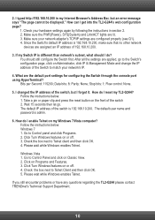
... then click Login. There are assigned an IP address of 192.168.10.200. (Refer to Troubleshooting section on your web browser, type http://192.168.10.200 in the subnet of configuring the TL2-G244: Web Browser, Console Port and Telnet. 1. By default: User Name: admin Password: admin 3. ...Before the Switch can be configured, a Static IP address must be assigned to configure TCP/IP settings on how to your computer's network adapter in the...
... then click Login. There are assigned an IP address of 192.168.10.200. (Refer to Troubleshooting section on your web browser, type http://192.168.10.200 in the subnet of configuring the TL2-G244: Web Browser, Console Port and Telnet. 1. By default: User Name: admin Password: admin 3. ...Before the Switch can be configured, a Static IP address must be assigned to configure TCP/IP settings on how to your computer's network adapter in the...
Quick Installation Guide
Page 12
...on my Windows 7/Vista computer? Wait 15 seconds then let go to match your network adapter's TCP/IP settings are applied, go . The default IP address of the switch 2. Follow the instructions below : 1. Go to Telnet client and then click ...default port settings for configuring the Switch through the console port using HyperTerminal? How do I get into the TL2-G244's web configuration page? 1. Check the box next to Control panel and click Programs. 2. Click on Classic View. 2. If you still encounter problems or have any questions regarding the TL2-G244 please contact TRENDnet...
...on my Windows 7/Vista computer? Wait 15 seconds then let go to match your network adapter's TCP/IP settings are applied, go . The default IP address of the switch 2. Follow the instructions below : 1. Go to Telnet client and then click ...default port settings for configuring the Switch through the console port using HyperTerminal? How do I get into the TL2-G244's web configuration page? 1. Check the box next to Control panel and click Programs. 2. Click on Classic View. 2. If you still encounter problems or have any questions regarding the TL2-G244 please contact TRENDnet...
