
Configuration Guide
Page 2
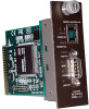
... of network operations. Figure 1. Connect the module to configure the Media Converter Chassis system. CONFIGURING THE SYSTEM This chapter provides network managers and system administrators with an understanding of this document should be a network administrator or manager with information about network devices, device configuration, network management, and Internet browsers. Slide in the management module in the first slot of the chassis system. Boot up for the management module as illustration on Web browser...
... of network operations. Figure 1. Connect the module to configure the Media Converter Chassis system. CONFIGURING THE SYSTEM This chapter provides network managers and system administrators with an understanding of this document should be a network administrator or manager with information about network devices, device configuration, network management, and Internet browsers. Slide in the management module in the first slot of the chassis system. Boot up for the management module as illustration on Web browser...
Configuration Guide
Page 3
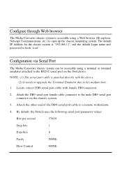
... serial port cable is both "root". Configuration via Serial Port The Media Converter chassis system can be accessible using a Web browser (IE explorer, Netscape Communications, etc.) to key malfunction. 1. The default IP Address for the chassis system is "192.168.1.1", and the default Login name and password is attached directly with female DB9 connector. 2. Locate correct DB9 serial port cable with the device. (2) It needs to upgrade the Terminal Emulator due to open...
... serial port cable is both "root". Configuration via Serial Port The Media Converter chassis system can be accessible using a Web browser (IE explorer, Netscape Communications, etc.) to key malfunction. 1. The default IP Address for the chassis system is "192.168.1.1", and the default Login name and password is attached directly with female DB9 connector. 2. Locate correct DB9 serial port cable with the device. (2) It needs to upgrade the Terminal Emulator due to open...
Configuration Guide
Page 4
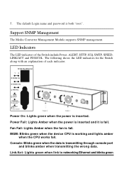
... Converter Management Module supports SNMP management. LED Indicators The LED indicators of each indicator. 10/100 Fast Ethernet 12 POWER ON POWER FAIL FAN FAIL MGM CPUWORK CPUFAIL CONSOLE DATA TRANSFER ERROR DATA LINK/ACT LINK DATA TRANSFER Power On: Lights green when the power is working and lights amber when the CPU works fail. Fan Fail: Lights Amber when the fan is fail. 5. Console: Blinks green when the data is both "root". The default Login name and password is...
... Converter Management Module supports SNMP management. LED Indicators The LED indicators of each indicator. 10/100 Fast Ethernet 12 POWER ON POWER FAIL FAN FAIL MGM CPUWORK CPUFAIL CONSOLE DATA TRANSFER ERROR DATA LINK/ACT LINK DATA TRANSFER Power On: Lights green when the power is working and lights amber when the CPU works fail. Fan Fail: Lights Amber when the fan is fail. 5. Console: Blinks green when the data is both "root". The default Login name and password is...
Configuration Guide
Page 5
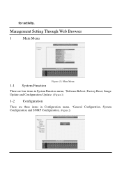
Management Setting Through Web Browser 1 Main Menu Figure (1) Main Menu 1-1 System Function There are four items in System Function menu, "Software Reboot, Factory Reset, Image Update and Configuration Update. (Figure 2) 1-2 Configuration There are three items in Configuration menu, "General Configuration, System Configuration and SNMP Configuration. (Figure 2) for activity.
Management Setting Through Web Browser 1 Main Menu Figure (1) Main Menu 1-1 System Function There are four items in System Function menu, "Software Reboot, Factory Reset, Image Update and Configuration Update. (Figure 2) 1-2 Configuration There are three items in Configuration menu, "General Configuration, System Configuration and SNMP Configuration. (Figure 2) for activity.
Configuration Guide
Page 6
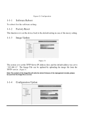
Figure (2) Configuration 1-1-1 Software Reboot To reboot for the software setting. 1-1-2 Factory Reset This function is to set the device back to the default setting in case of the management module, please be sure that the image file is to set the TFTP Server IP Address first, and the default address was set to "192.168.1.2". The Image File can be updated by uploading the image file from the TFTP server. (Figure 3) Note: The content of the image file will write the whole firmware of the messy setting. 1-1-3 Image Update Figure (3) The section is correct. 1-1-4 Configuration Update
Figure (2) Configuration 1-1-1 Software Reboot To reboot for the software setting. 1-1-2 Factory Reset This function is to set the device back to the default setting in case of the management module, please be sure that the image file is to set the TFTP Server IP Address first, and the default address was set to "192.168.1.2". The Image File can be updated by uploading the image file from the TFTP server. (Figure 3) Note: The content of the image file will write the whole firmware of the messy setting. 1-1-3 Image Update Figure (3) The section is correct. 1-1-4 Configuration Update
Configuration Guide
Page 7
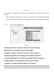
.... The Configuration Download is to restore a setting file to backup the setting from the management module. 1-2-1 General Configuration Figure (5) Hardware revision: noted the version of the hardware. Refresh time: to authorize the device system name. The Configuration Upload is to the management module. BIOS revision: noted the version of the firmware. System Name: to set the refreshing time of the module. Confirm Password: to upload and download the configure setting of the device through the web. Change Password: the changing of admit password...
.... The Configuration Download is to restore a setting file to backup the setting from the management module. 1-2-1 General Configuration Figure (5) Hardware revision: noted the version of the hardware. Refresh time: to authorize the device system name. The Configuration Upload is to the management module. BIOS revision: noted the version of the firmware. System Name: to set the refreshing time of the module. Confirm Password: to upload and download the configure setting of the device through the web. Change Password: the changing of admit password...

Configuration Guide
Page 8
1-2-2 General Configuration Figure (6) MAC Address: will show out the MAC address of the device. Subnet Mask: to allocate an IP address for the device, the default IP is "255.255.255.0". NOTE: After configuring the system device, need to press the save button to set the Subnet Mask, the default is "192.168.1.1". IP Address: to set the gateway address, the default is "192.168.1.254". Default Gateway: to save the setting.
1-2-2 General Configuration Figure (6) MAC Address: will show out the MAC address of the device. Subnet Mask: to allocate an IP address for the device, the default IP is "255.255.255.0". NOTE: After configuring the system device, need to press the save button to set the Subnet Mask, the default is "192.168.1.1". IP Address: to set the gateway address, the default is "192.168.1.254". Default Gateway: to save the setting.

Configuration Guide
Page 9
... Converter module if it is plugged in (default = enable). Fan Fail Trap: to set the fan fail trap (default = enable). 1-2-3 SNMP Configuration Figure (7) Get Community Name: to authorize the device trap community name (default = public) . Trap Community Name: to get the device community name (default=public). Trap Host IP Address: to set the trap host IP address (sameasmonitoringstation IP address). Power Fail Trap: to set the Power Fail Trap (default = enable). MC Plug-in Trap: to set the...
... Converter module if it is plugged in (default = enable). Fan Fail Trap: to set the fan fail trap (default = enable). 1-2-3 SNMP Configuration Figure (7) Get Community Name: to authorize the device trap community name (default = public) . Trap Community Name: to get the device community name (default=public). Trap Host IP Address: to set the trap host IP address (sameasmonitoringstation IP address). Power Fail Trap: to set the Power Fail Trap (default = enable). MC Plug-in Trap: to set the...
Configuration Guide
Page 10
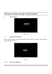
Management Setting Through Terminal Emulator 2 Main Menu Figure (8) 2-1 System Function There are three items in System Function menu, "Software Reboot, Factory Reset, Image Update. (Figure 9) 2-1-1 Software Reboot Figure (9)
Management Setting Through Terminal Emulator 2 Main Menu Figure (8) 2-1 System Function There are three items in System Function menu, "Software Reboot, Factory Reset, Image Update. (Figure 9) 2-1-1 Software Reboot Figure (9)
Configuration Guide
Page 11
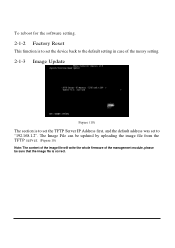
The Image File can be updated by uploading the image file from the TFTP server. (Figure 10) Note: The content of the image file will write the whole firmware of the management module, please be sure that the image file is to set the TFTP Server IP Address first, and the default address was set the device back to "192.168.1.2". To reboot for the software setting. 2-1-2 Factory Reset This function is to set to the default setting in case of the messy setting. 2-1-3 Image Update Figure (10) The section is correct.
The Image File can be updated by uploading the image file from the TFTP server. (Figure 10) Note: The content of the image file will write the whole firmware of the management module, please be sure that the image file is to set the TFTP Server IP Address first, and the default address was set the device back to "192.168.1.2". To reboot for the software setting. 2-1-2 Factory Reset This function is to set to the default setting in case of the messy setting. 2-1-3 Image Update Figure (10) The section is correct.
Configuration Guide
Page 12
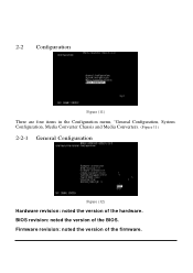
BIOS revision: noted the version of the firmware. Firmware revision: noted the version of the BIOS. 2-2 Configuration Figure (11) There are four items in the Configuration menu, "General Configuration, System Configuration, Media Converter Chassis and Media Converters. (Figure 11) 2-2-1 General Configuration Figure (12) Hardware revision: noted the version of the hardware.
BIOS revision: noted the version of the firmware. Firmware revision: noted the version of the BIOS. 2-2 Configuration Figure (11) There are four items in the Configuration menu, "General Configuration, System Configuration, Media Converter Chassis and Media Converters. (Figure 11) 2-2-1 General Configuration Figure (12) Hardware revision: noted the version of the hardware.

Configuration Guide
Page 13
... the device through the web. 2-2-2 System Configuration Figure (13) MAC Address: will show the device where it is "192.168.1.254". Location: to confirm the setting of the admit password. Default GW: to set the gateway address, the default is located. Refresh time: to set the refreshing time of the device. Subnet Mask: to allocate an IP address for the device, the default IP is "255.255.255.0". NOTE: After configuring the system device, need...
... the device through the web. 2-2-2 System Configuration Figure (13) MAC Address: will show the device where it is "192.168.1.254". Location: to confirm the setting of the admit password. Default GW: to set the gateway address, the default is located. Refresh time: to set the refreshing time of the device. Subnet Mask: to allocate an IP address for the device, the default IP is "255.255.255.0". NOTE: After configuring the system device, need...

Configuration Guide
Page 14
V stands for "yes" and X stands for "No". Fan Fail: indicates if the Fan 1 or 2 is fail or not. Power Fail: indicates if the Power 1 or 2 is fail or not. 2-2-3 Media Converter Chassis Figure (14) The screen will show out the power status of the chassis system. Plug in: indicates if Power 1 or 2 was plugged in or not.
V stands for "yes" and X stands for "No". Fan Fail: indicates if the Fan 1 or 2 is fail or not. Power Fail: indicates if the Power 1 or 2 is fail or not. 2-2-3 Media Converter Chassis Figure (14) The screen will show out the power status of the chassis system. Plug in: indicates if Power 1 or 2 was plugged in or not.

Configuration Guide
Page 15
2-2-4 Media Converters Figure (15) Indicates the Link, Duplex mode and Speed status of each media converter.
2-2-4 Media Converters Figure (15) Indicates the Link, Duplex mode and Speed status of each media converter.

Configuration Guide
Page 16
... Host IP Address: to set the fan fail trap (default = enable). Fan Fail Trap: to set the trap host IP address (sameasmonitoringstation IP address). MC Pullout Trap: to set the trap of the device and workstation are different (default = enable). Trap Community Name: to set the trap for rebooting the device (default = enable). Cold Start trap: to authorize the device trap community name (default = public) . 2-3 SNMP Configuration Figure (16) Get Community Name: to set the device...
... Host IP Address: to set the fan fail trap (default = enable). Fan Fail Trap: to set the trap host IP address (sameasmonitoringstation IP address). MC Pullout Trap: to set the trap of the device and workstation are different (default = enable). Trap Community Name: to set the trap for rebooting the device (default = enable). Cold Start trap: to authorize the device trap community name (default = public) . 2-3 SNMP Configuration Figure (16) Get Community Name: to set the device...
Configuration Guide
Page 17
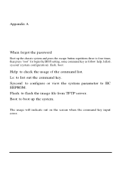
Flash: to list out the command key. Ls: to flash the image file from TFTP server. Appendix A When forgot the password Boot up the chassis system and press the escape button repetitious three to four times, then press "root" for login the BIOS setting, some command key as follow: help, ls(list), sysconf (system configuration), flash, boot Help: to boot up the system. Boot: to check the usage of the command list. The usage will indicate out on the screen when the command key input error. Sysconf: to configure or view the system parameter to IIC EEPROM.
Flash: to list out the command key. Ls: to flash the image file from TFTP server. Appendix A When forgot the password Boot up the chassis system and press the escape button repetitious three to four times, then press "root" for login the BIOS setting, some command key as follow: help, ls(list), sysconf (system configuration), flash, boot Help: to boot up the system. Boot: to check the usage of the command list. The usage will indicate out on the screen when the command key input error. Sysconf: to configure or view the system parameter to IIC EEPROM.


