
User's Guide
Page 5
TABLE OF CONTENT About This Guide 1 Purpose 1 Terms/Usage 1 Introduction 3 Gigabit Ethernet Technology 3 Fast Ethernet Technology 4 Switching Technology 5 VLAN (Virtual Local Area Network 6 Features 6 Unpacking and Installation 9 Unpacking 9 Installation 9 Rack Mounting 10 Connecting Network Cable 11 AC Power 11 Identifying External Components 13 Front Panel 13 Rear Panel 14 Understanding LED Indicators 15 Power and System LEDs 15 Ports 1~24 10/100M Status LEDs 16 Ports 25~26 Gigabit Status LEDs 16 Ports 27~28 mini-GBIC Status LEDs 17 i
TABLE OF CONTENT About This Guide 1 Purpose 1 Terms/Usage 1 Introduction 3 Gigabit Ethernet Technology 3 Fast Ethernet Technology 4 Switching Technology 5 VLAN (Virtual Local Area Network 6 Features 6 Unpacking and Installation 9 Unpacking 9 Installation 9 Rack Mounting 10 Connecting Network Cable 11 AC Power 11 Identifying External Components 13 Front Panel 13 Rear Panel 14 Understanding LED Indicators 15 Power and System LEDs 15 Ports 1~24 10/100M Status LEDs 16 Ports 25~26 Gigabit Status LEDs 16 Ports 27~28 mini-GBIC Status LEDs 17 i
User's Guide
Page 6
Configuration 19 Installing the Web Management Utility 19 Discovery List 20 Monitor List 21 Device Setting 23 Toolbar 24 Configuring the Switch 25 Login 26 Setup Menu 28 Configuring Setup Setting 28 Port Settings 28 VLAN Settings (Virtual Local Area Network 30 Trunk Setting 31 Mirror Setting 31 Device Status 32 Statistic 32 System Setting 34 Trap Setting 34 Set Password 35 Backup Setting 36 Reset Setting 37 Logout 37 Technical Specifications 39 ii
Configuration 19 Installing the Web Management Utility 19 Discovery List 20 Monitor List 21 Device Setting 23 Toolbar 24 Configuring the Switch 25 Login 26 Setup Menu 28 Configuring Setup Setting 28 Port Settings 28 VLAN Settings (Virtual Local Area Network 30 Trunk Setting 31 Mirror Setting 31 Device Status 32 Statistic 32 System Setting 34 Trap Setting 34 Set Password 35 Backup Setting 36 Reset Setting 37 Logout 37 Technical Specifications 39 ii

User's Guide
Page 9
..., full duplex, flow control, and management objects, but with all 10-Mbps and 100-Mbps Ethernet environments, Gigabit Ethernet provides a straightforward upgrade without wasting a company's existing investment in theoretical throughput over 100-Mbps Fast Ethernet and a hundredfold increase over 10-Mbps Ethernet. Gigabit Ethernet enables fast optical fiber connections to Gigabit Ethernet can greatly improve network response times as well as computers and their busses get faster and more users use applications that...
..., full duplex, flow control, and management objects, but with all 10-Mbps and 100-Mbps Ethernet environments, Gigabit Ethernet provides a straightforward upgrade without wasting a company's existing investment in theoretical throughput over 100-Mbps Fast Ethernet and a hundredfold increase over 10-Mbps Ethernet. Gigabit Ethernet enables fast optical fiber connections to Gigabit Ethernet can greatly improve network response times as well as computers and their busses get faster and more users use applications that...
User's Guide
Page 11
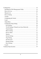
... forwards traffic that needs to go from one segment to users on a local area network. A switch bridges Ethernet packets at the MAC address level of increasing the total network capacity available to another. A switch increases capacity and decreases network loading by dividing a local area network into different segments, which were characterized by higher latencies. Switching is multiplied, while still maintaining the same network cabling and adapter cards...
... forwards traffic that needs to go from one segment to users on a local area network. A switch bridges Ethernet packets at the MAC address level of increasing the total network capacity available to another. A switch increases capacity and decreases network loading by dividing a local area network into different segments, which were characterized by higher latencies. Switching is multiplied, while still maintaining the same network cabling and adapter cards...
User's Guide
Page 12
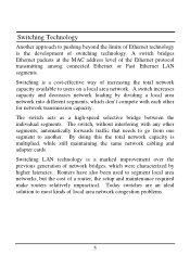
... of using VLAN is to reduce latency and need to use cross-over cables or an up-link port Full/half duplex transfer mode for 10/100Mbps RJ45 port Full duplex transfer mode for routers, using faster switching instead. VLAN (Virtual Local Area Network) A VLAN is a group of end-stations that are not constrained by their physical location and can be switched to support rate adaptation and ensure data integrity 6 Other VLAN utility...
... of using VLAN is to reduce latency and need to use cross-over cables or an up-link port Full/half duplex transfer mode for 10/100Mbps RJ45 port Full duplex transfer mode for routers, using faster switching instead. VLAN (Virtual Local Area Network) A VLAN is a group of end-stations that are not constrained by their physical location and can be switched to support rate adaptation and ensure data integrity 6 Other VLAN utility...
User's Guide
Page 13
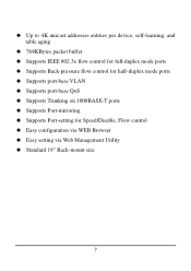
Up to 4K unicast addresses entities per device, self-learning, and table aging 768KBytes packet buffer Supports IEEE 802.3x flow control for full-duplex mode ports Supports Back-pressure flow control for half-duplex mode ports Supports port-base VLAN Supports port-base QoS Supports Trunking on 1000BASE-T ports Supports Port-mirroring Supports Port-setting for Speed/Disable, Flow control Easy configuration via WEB Browser Easy setting via Web Management Utility Standard 19" Rack-mount size 7
Up to 4K unicast addresses entities per device, self-learning, and table aging 768KBytes packet buffer Supports IEEE 802.3x flow control for full-duplex mode ports Supports Back-pressure flow control for half-duplex mode ports Supports port-base VLAN Supports port-base QoS Supports Trunking on 1000BASE-T ports Supports Port-mirroring Supports Port-setting for Speed/Disable, Flow control Easy configuration via WEB Browser Easy setting via Web Management Utility Standard 19" Rack-mount size 7

User's Guide
Page 15
... with Web Management Utility and User's Guide If any item is found missing or damaged, please contact your local reseller for the acceptable temperature and humidity operating ranges. See Technical Specifications for replacement. UNPACKING AND INSTALLATION This chapter provides unpacking and installation information for the Switch. When installing, consider the following items: One 24+4G-Port 10/100/1000Mbps Gigabit Ethernet Web Smart Switch One AC power...
... with Web Management Utility and User's Guide If any item is found missing or damaged, please contact your local reseller for the acceptable temperature and humidity operating ranges. See Technical Specifications for replacement. UNPACKING AND INSTALLATION This chapter provides unpacking and installation information for the Switch. When installing, consider the following items: One 24+4G-Port 10/100/1000Mbps Gigabit Ethernet Web Smart Switch One AC power...

User's Guide
Page 17
... system fan. There are Auto-MDI type port. The power switch is located at the rear of the unit adjacent to the local power source automatically and may be turned on without worrying if you are using a standard or crossover RJ45 cable. Connecting Network Cable The Switch supports 10Mbps Ethernet or 100Mbps Fast Ethernet and it runs both in half and full duplex mode and 1000Mbps Gigabit Ethernet runs in full duplex mode using four...
... system fan. There are Auto-MDI type port. The power switch is located at the rear of the unit adjacent to the local power source automatically and may be turned on without worrying if you are using a standard or crossover RJ45 cable. Connecting Network Cable The Switch supports 10Mbps Ethernet or 100Mbps Fast Ethernet and it runs both in half and full duplex mode and 1000Mbps Gigabit Ethernet runs in full duplex mode using four...

User's Guide
Page 19
... half-duplex mode for 10/100/1000Mbps. 13 Front panel of 24+4G-port Gigabit Ethernet Switch LED Indicator: Comprehensive LED indicators display the status of the switch and the network (see the LED Indicators chapter below shows the front panels of the Switch. 28-Port 10/100/1000Mbps Web-SMART Gigabit Ethernet Switch 10/100M 1 3 5 7 9 11 13 15 17 19 21 23 Link/ACT Gigabit 25 26 27 28 Link/ACT POWER...
... half-duplex mode for 10/100/1000Mbps. 13 Front panel of 24+4G-port Gigabit Ethernet Switch LED Indicator: Comprehensive LED indicators display the status of the switch and the network (see the LED Indicators chapter below shows the front panels of the Switch. 28-Port 10/100/1000Mbps Web-SMART Gigabit Ethernet Switch 10/100M 1 3 5 7 9 11 13 15 17 19 21 23 Link/ACT Gigabit 25 26 27 28 Link/ACT POWER...

User's Guide
Page 21
...Management Indicator Blinking : When the CPU is working, the System LED is not working. 15 UNDERSTANDING LED INDICATORS The front panel LEDs provides instant status feedback, and, helps monitor and troubleshoot when needed. 28-2P4o-Protrt1100/1100M0b/1ps0E0t0hMernbept SsmWarteSbw-iStchMART Gigabit Ethernet Switch 10/100M Gigabit 1 Link/ACT FX 1 PPOOWEWRER Link... blinking. Off : When the Power turns off or the power cord has improper connection. LED indicators of the Switch Power and System LEDs POWER: Power Indicator On : When the Power LED lights on, the Switch is receiving...
...Management Indicator Blinking : When the CPU is working, the System LED is not working. 15 UNDERSTANDING LED INDICATORS The front panel LEDs provides instant status feedback, and, helps monitor and troubleshoot when needed. 28-2P4o-Protrt1100/1100M0b/1ps0E0t0hMernbept SsmWarteSbw-iStchMART Gigabit Ethernet Switch 10/100M Gigabit 1 Link/ACT FX 1 PPOOWEWRER Link... blinking. Off : When the Power turns off or the power cord has improper connection. LED indicators of the Switch Power and System LEDs POWER: Power Indicator On : When the Power LED lights on, the Switch is receiving...

User's Guide
Page 23
... connected to a 1000Mbps Gigabit Ethernet network. 100Mbps On : When the 100Mbps LED lights on, the respective port is connected to a 1000Mbps Gigabit Ethernet network. Off : No link. 1000Mbps On : When the 1000Mbps LED lights on . Off : When the respective port is installed and connected to a network, the Link/ACT LED lights on , the respective port is connected to the network 17 Off : When the respective port is connected to a 10Mbps Ethernet or 100Mbps Fast Ethernet network Ports 27~28 mini-GBIC Status LEDs Link...
... connected to a 1000Mbps Gigabit Ethernet network. 100Mbps On : When the 100Mbps LED lights on, the respective port is connected to a 1000Mbps Gigabit Ethernet network. Off : No link. 1000Mbps On : When the 1000Mbps LED lights on . Off : When the respective port is installed and connected to a network, the Link/ACT LED lights on , the respective port is connected to the network 17 Off : When the respective port is connected to a 10Mbps Ethernet or 100Mbps Fast Ethernet network Ports 27~28 mini-GBIC Status LEDs Link...
User's Guide
Page 25
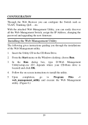
... can configure the Switch such as VLAN, Trunking, QoS... Installing the Web Management Utility The following gives instructions guiding you through the installations of the Web Management utility. 1. In the Run dialog box, type D:\Web Management Utility\setup.exe (D:\ depends where your CD-Rom drive is located) and click OK. 4. CONFIGURATION Through the Web Browser you can easily discover all the Web Management Switch, assign the IP Address, changing the password and upgrading the new firmware. From...
... can configure the Switch such as VLAN, Trunking, QoS... Installing the Web Management Utility The following gives instructions guiding you through the installations of the Web Management utility. 1. In the Run dialog box, type D:\Web Management Utility\setup.exe (D:\ depends where your CD-Rom drive is located) and click OK. 4. CONFIGURATION Through the Web Browser you can easily discover all the Web Management Switch, assign the IP Address, changing the password and upgrading the new firmware. From...
User's Guide
Page 27
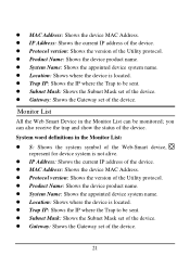
... is located. Gateway: Shows the Gateway set of the device. Protocol version: Shows the version of the device. Subnet Mask: Shows the Subnet Mask set of the device. IP Address: Shows the current IP address of the Utility protocol. MAC Address: Shows the device MAC Address. Product Name... name. Gateway: Shows the Gateway set of the device. 21 System word definitions in the Monitor List can also receive the trap and show the status of the Web-Smart device, represent for device system is not alive. Monitor List All the Web Smart Device in the Monitor List: S: Shows...
... is located. Gateway: Shows the Gateway set of the device. Protocol version: Shows the version of the device. Subnet Mask: Shows the Subnet Mask set of the device. IP Address: Shows the current IP address of the Utility protocol. MAC Address: Shows the device MAC Address. Product Name... name. Gateway: Shows the Gateway set of the device. 21 System word definitions in the Monitor List can also receive the trap and show the status of the Web-Smart device, represent for device system is not alive. Monitor List All the Web Smart Device in the Monitor List: S: Shows...
User's Guide
Page 28
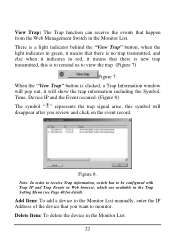
... the Web Management Switch in the Trap Setting Menu (see Page 40 for detail). Figure 8. Note: In order to receive Trap information, switch has to view the trap. (Figure 7) Figure 7. There is a light indicator behind the "View Trap" button, when the light indicates in green, it means that there is no trap transmitted, and else when it indicates in the Monitor List. 22...
... the Web Management Switch in the Trap Setting Menu (see Page 40 for detail). Figure 8. Note: In order to receive Trap information, switch has to view the trap. (Figure 7) Figure 7. There is a light indicator behind the "View Trap" button, when the light indicates in green, it means that there is no trap transmitted, and else when it indicates in the Monitor List. 22...

User's Guide
Page 29
... Address), System name and Location. Select the device in the Discovery list or Monitor List and press this Password Change when you need to change the password, fill in the password needed in the Device Setting Dialog box. Figure 9. Configuration Setting Password Change: You can set the device by using the function key in the dialog box and press "Set" button to proceed the password change , you can use this button, then the Configuration Setting window...
... Address), System name and Location. Select the device in the Discovery list or Monitor List and press this Password Change when you need to change the password, fill in the password needed in the Device Setting Dialog box. Figure 9. Configuration Setting Password Change: You can set the device by using the function key in the dialog box and press "Set" button to proceed the password change , you can use this button, then the Configuration Setting window...
User's Guide
Page 31
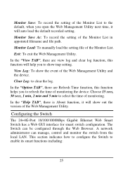
... you open the Web Management Utility next time, it will auto load the default recorded setting. Clear Log: to enable its smart functions including: 25 Configuring the Switch The 24+4G-Port 10/100/1000Mbps Gigabit Ethernet Web Smart Switch has a Web GUI interface for smart switch configuration. This section indicates how to configure the Switch to clear the log. A network administrator can be configured through the Web Browser. Monitor Load: To manually load the setting file of monitoring. The Switch can manage, control and monitor the switch from the...
... you open the Web Management Utility next time, it will auto load the default recorded setting. Clear Log: to enable its smart functions including: 25 Configuring the Switch The 24+4G-Port 10/100/1000Mbps Gigabit Ethernet Web Smart Switch has a Web GUI interface for smart switch configuration. This section indicates how to configure the Switch to clear the log. A network administrator can be configured through the Web Browser. Monitor Load: To manually load the setting file of monitoring. The Switch can manage, control and monitor the switch from the...
User's Guide
Page 32
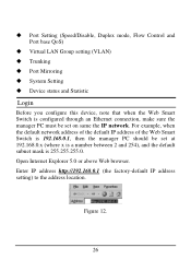
... factory-default IP address setting) to the address location. For example, when the default network address of the default IP address of the Web Smart Switch is 192.168.0.1, then the manager PC should be set at 192.168.0.x (where x is a number between 2 and 254), and the default subnet mask is configured through an Ethernet connection, make sure the manager PC must be set on same the IP network. Port Setting (Speed/Disable, Duplex mode, Flow Control and Port base QoS) Virtual LAN Group setting (VLAN) Trunking Port Mirroring...
... factory-default IP address setting) to the address location. For example, when the default network address of the default IP address of the Web Smart Switch is 192.168.0.1, then the manager PC should be set at 192.168.0.x (where x is a number between 2 and 254), and the default subnet mask is configured through an Ethernet connection, make sure the manager PC must be set on same the IP network. Port Setting (Speed/Disable, Duplex mode, Flow Control and Port base QoS) Virtual LAN Group setting (VLAN) Trunking Port Mirroring...
User's Guide
Page 37
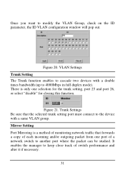
... that forwards a copy of each incoming and/or outgoing packet from one selection for the trunk setting, port 25 and port 26, or select "disable" for closing this function. VLAN Settings Trunk Setting The Trunk function enables to cascade two devices with a double times bandwidth (up to the device with a same VLAN group. There is a method of monitoring network traffic that the selected trunk setting port must connect to 4000Mbps in full duplex mode...
... that forwards a copy of each incoming and/or outgoing packet from one selection for the trunk setting, port 25 and port 26, or select "disable" for closing this function. VLAN Settings Trunk Setting The Trunk function enables to cascade two devices with a double times bandwidth (up to the device with a same VLAN group. There is a method of monitoring network traffic that the selected trunk setting port must connect to 4000Mbps in full duplex mode...

User's Guide
Page 41
... be login. will restore to change the password. Abnormal* Receive Error: a trap when there are transmit data error in fiber port. Fiber Port Events: Monitoring the Fiber port status. Set Password Password is linking status happens in fiber port. Abnormal* Transmit Error: a trap when there are receive data error in the rear panel of the Switch, the current setting includes VLAN, Port Setting... Link Up/Link Down: a trap when there is the invaluable tool for the manager to secure Web Management Switch, use this function to the default setting...
... be login. will restore to change the password. Abnormal* Receive Error: a trap when there are transmit data error in fiber port. Fiber Port Events: Monitoring the Fiber port status. Set Password Password is linking status happens in fiber port. Abnormal* Transmit Error: a trap when there are receive data error in the rear panel of the Switch, the current setting includes VLAN, Port Setting... Link Up/Link Down: a trap when there is the invaluable tool for the manager to secure Web Management Switch, use this function to the default setting...

User's Guide
Page 43
Reset Setting The Factory Reset button helps you to reset the device back to default setting 192.168.0.1. Be aware that the entire configuration will be reset, the IP address of the device will go back to first Login page. Figure 30. Figure 29. Logout 37 Reset Setting Logout When press this function, the web configuration will be set to the default setting from the factory.
Reset Setting The Factory Reset button helps you to reset the device back to default setting 192.168.0.1. Be aware that the entire configuration will be reset, the IP address of the device will go back to first Login page. Figure 30. Figure 29. Logout 37 Reset Setting Logout When press this function, the web configuration will be set to the default setting from the factory.


