DW-224E-V Brochure
Page 1
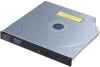
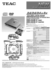
... 1107 PDF . Features andspecifications are the respective trademarks orregistered trademarks ofthe companies mentioned. TEAC® Al COMPACT -g z z A-9 z ,> (7. > / MBE ReWritable 5 ROM CD-RiiVe arf i-ii)±:j_i_V CD Recordable/Rewritable and DVD-ROM DRIVE Suitable for Notebook PCs DW-224E-V (IDE) DW-224S-V (SATA) • Standard half inch design • Buffer underrun Prevention • Supporting...
... 1107 PDF . Features andspecifications are the respective trademarks orregistered trademarks ofthe companies mentioned. TEAC® Al COMPACT -g z z A-9 z ,> (7. > / MBE ReWritable 5 ROM CD-RiiVe arf i-ii)±:j_i_V CD Recordable/Rewritable and DVD-ROM DRIVE Suitable for Notebook PCs DW-224E-V (IDE) DW-224S-V (SATA) • Standard half inch design • Buffer underrun Prevention • Supporting...
Hardware Specification
Page 1
TEAC DW-224E-R93 CD-RW/DVD-ROM DRIVE HARDWARE SPECIFICATION Rev. A 34 sheets in Total 7757a
TEAC DW-224E-R93 CD-RW/DVD-ROM DRIVE HARDWARE SPECIFICATION Rev. A 34 sheets in Total 7757a
Hardware Specification
Page 2
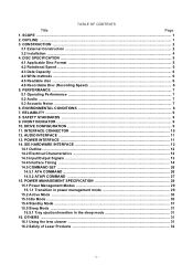
CONSTRUCTION ...2 3.1 External Construction ...2 3.2 Installation ...4 4. IDE HARDWARE INTERFACE 12 14.1 Outline ...12 14.2 Electrical Characteristics 12 14.3 Input/Output Signals ...13 14.4 Interface Timing ...14 14.5 COMMAND SET ...26 14.5.1 ATA COMMAND ...26 14.5.2 ATAPI COMMAND ...27 15. SCOPE ...1 2. DISC SPECIFICATION ...5 4.1 Applicable Disc Format ...5 4.2 Rotational Speed ...5 4.3 Data Capacity ...6 4.4 Write methods ...6 4.5 Readable disc ...6 4.6 Recordable Disc (Recording Speed 6 5. TABLE OF CONTENTS Title Page 1. ENVIRONMENTAL CONDITIONS 8...
CONSTRUCTION ...2 3.1 External Construction ...2 3.2 Installation ...4 4. IDE HARDWARE INTERFACE 12 14.1 Outline ...12 14.2 Electrical Characteristics 12 14.3 Input/Output Signals ...13 14.4 Interface Timing ...14 14.5 COMMAND SET ...26 14.5.1 ATA COMMAND ...26 14.5.2 ATAPI COMMAND ...27 15. SCOPE ...1 2. DISC SPECIFICATION ...5 4.1 Applicable Disc Format ...5 4.2 Rotational Speed ...5 4.3 Data Capacity ...6 4.4 Write methods ...6 4.5 Readable disc ...6 4.6 Recordable Disc (Recording Speed 6 5. TABLE OF CONTENTS Title Page 1. ENVIRONMENTAL CONDITIONS 8...
Hardware Specification
Page 3
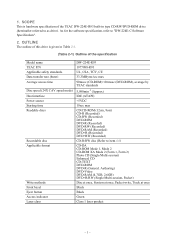
... given in type CD-RW/DVD-ROM drive (hereinafter referred to "DW-224E-C Software Specification". 2. As for the software specification, refer to as drive). OUTLINE The outline of this drive is hardware specification of the TEAC DW-224E-R93 built-in Table 2-1. (Table 2-1) Outline of the specification Model... name TEAC P/N Applicable safety standards Data transfer rate (burst) Average access time Disc speed (24X CAV...
... given in type CD-RW/DVD-ROM drive (hereinafter referred to "DW-224E-C Software Specification". 2. As for the software specification, refer to as drive). OUTLINE The outline of this drive is hardware specification of the TEAC DW-224E-R93 built-in Table 2-1. (Table 2-1) Outline of the specification Model... name TEAC P/N Applicable safety standards Data transfer rate (burst) Average access time Disc speed (24X CAV...
Hardware Specification
Page 4
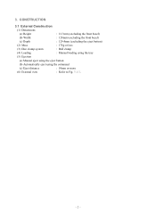
CONSTRUCTION 3.1 External Construction (1) Dimensions (a) Height : 12.7mm (excluding the front bezel) (b) Width : 128mm (excluding the front bezel) (c) Depth : 129.4mm (excluding the eject button) (2) Mass : 178g or less (3) Disc clamp system : Ball clamp (4) Loading : Manual loading using the tray (5) Ejection (a) Manual eject using the eject button (b) Automatically eject using the command (c) Eject distance : 10mm or more (6) External view : Refer to Fig. 3.1-1. - 2 - 3.
CONSTRUCTION 3.1 External Construction (1) Dimensions (a) Height : 12.7mm (excluding the front bezel) (b) Width : 128mm (excluding the front bezel) (c) Depth : 129.4mm (excluding the eject button) (2) Mass : 178g or less (3) Disc clamp system : Ball clamp (4) Loading : Manual loading using the tray (5) Ejection (a) Manual eject using the eject button (b) Automatically eject using the command (c) Eject distance : 10mm or more (6) External view : Refer to Fig. 3.1-1. - 2 - 3.
Hardware Specification
Page 5
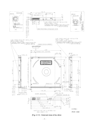
(Fig. 3.1-1) External view of the drive - 3 - ( ± 0.4 ) (Unit : mm)
(Fig. 3.1-1) External view of the drive - 3 - ( ± 0.4 ) (Unit : mm)
Hardware Specification
Page 6
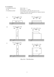
3.2 Installation (1) Installation direction (2) Tilt (3) Installation method : Refer to Fig. 3.2-1 : Refer to Fig. 3.2-1 below. : The fixing holes in the side of the drive - 4 - Separate discussions and arrangements are required when the installation holes are not used. (a) 30° or less 30° or less 30° or less 30° or less (b) 0° or less 30° or less 30° or less 30° or less (c) 30° or less 0° or less 30° or less 30° or less (Fig. 3.2-1) Tilt of the unit are used.
3.2 Installation (1) Installation direction (2) Tilt (3) Installation method : Refer to Fig. 3.2-1 : Refer to Fig. 3.2-1 below. : The fixing holes in the side of the drive - 4 - Separate discussions and arrangements are required when the installation holes are not used. (a) 30° or less 30° or less 30° or less 30° or less (b) 0° or less 30° or less 30° or less 30° or less (c) 30° or less 0° or less 30° or less 30° or less (Fig. 3.2-1) Tilt of the unit are used.
Hardware Specification
Page 7
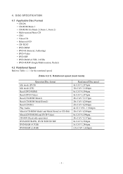
DISC SPECIFICATION 4.1 Applicable Disc Format • CD-DA • CD-ROM Mode 1 • CD-ROM XA Mode 2 (Form 1, Form 2) • Multi-session Photo CD • CD-I • Video CD • Enhanced CD • CD-TEXT • DVD-ROM • DVD-R (General, Authoring) • DVD-Video • DVD-RW • DVD-RAM (4.7GB, 2.6GB) • DVD+R/RW (Single/Multi-session, Packet) 4.2 Rotational Speed Refer to Table 4.2-1 for the rotational speed. (Table 4.2-1) Rotational speed (read mode) Operation/Disc format Idle mode (DVD) Idle mode (CD) Read (DVD-ROM) Read (DVD-Video) Read (CD-ROM ...
DISC SPECIFICATION 4.1 Applicable Disc Format • CD-DA • CD-ROM Mode 1 • CD-ROM XA Mode 2 (Form 1, Form 2) • Multi-session Photo CD • CD-I • Video CD • Enhanced CD • CD-TEXT • DVD-ROM • DVD-R (General, Authoring) • DVD-Video • DVD-RW • DVD-RAM (4.7GB, 2.6GB) • DVD+R/RW (Single/Multi-session, Packet) 4.2 Rotational Speed Refer to Table 4.2-1 for the rotational speed. (Table 4.2-1) Rotational speed (read mode) Operation/Disc format Idle mode (DVD) Idle mode (CD) Read (DVD-ROM) Read (DVD-Video) Read (CD-ROM ...
Hardware Specification
Page 8
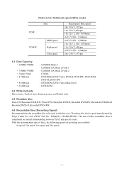
... the recommended type of discs, the following speeds of other recordable discs is a 79-minute disc for 8x speed manufactured by Taiyo Yuden Co., Ltd. (TEAC Part No.: T0006613, CD-R80-BULK). (Table 4.2-2) Rotational speed (Write mode) CD-R CD-RW Disc Multi speed High speed Ultra speed Read speed/ Disc speed... DVD+R, Recorded DVD+RW 4.6 Recordable Disc (Recording Speed) Recommended as the recordable disc to be used in this drive is conditional on mutual understanding between TEAC and specific users. The use of recording are available: 4x speed, 10x speed, 16x speed and 24x speed - 6 -
... the recommended type of discs, the following speeds of other recordable discs is a 79-minute disc for 8x speed manufactured by Taiyo Yuden Co., Ltd. (TEAC Part No.: T0006613, CD-R80-BULK). (Table 4.2-2) Rotational speed (Write mode) CD-R CD-RW Disc Multi speed High speed Ultra speed Read speed/ Disc speed... DVD+R, Recorded DVD+RW 4.6 Recordable Disc (Recording Speed) Recommended as the recordable disc to be used in this drive is conditional on mutual understanding between TEAC and specific users. The use of recording are available: 4x speed, 10x speed, 16x speed and 24x speed - 6 -
Hardware Specification
Page 9
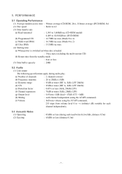
5. variable for each channel independently. 5.3 Acoustic Noise (1) Operating (2) Ejecting : 45dBA or less (during audio play. (a) Number of channels : 2 channels (stereo) (b) Frequency response : 20 to 20kHz (±3dB) (c) Dynamic range : 83dB or more (IHF A, 1kHz, LPF 20kHz) (d) S/N : 85dB or more (IHF A, 1kHz, LPF 20kHz) (e) Distortion factor : 0.05% or less (1kHz, 20kHz LPF) (f) Channel separation : 70dB or more (1kHz, 20kHz LPF) (g) Output level : 0.8Vrms ±3dB (load = 47kΩ ATT = 0dB) (h) Muting : each channel independent (using the ATAPI command) (i) Volume...
5. variable for each channel independently. 5.3 Acoustic Noise (1) Operating (2) Ejecting : 45dBA or less (during audio play. (a) Number of channels : 2 channels (stereo) (b) Frequency response : 20 to 20kHz (±3dB) (c) Dynamic range : 83dB or more (IHF A, 1kHz, LPF 20kHz) (d) S/N : 85dB or more (IHF A, 1kHz, LPF 20kHz) (e) Distortion factor : 0.05% or less (1kHz, 20kHz LPF) (f) Channel separation : 70dB or more (1kHz, 20kHz LPF) (g) Output level : 0.8Vrms ±3dB (load = 47kΩ ATT = 0dB) (h) Muting : each channel independent (using the ATAPI command) (i) Volume...
Hardware Specification
Page 10
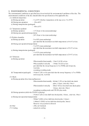
ENVIRONMENTAL CONDITIONS The environmental conditions as specified here do not include the environmental conditions of the applicable disc. (1) Ambient temperature (a) During operation : 5 to 45°C (Surface temperature on the top cover; 5 to 50°C) (b) During non-operation : -20 to 60°C (c) During transportation (packaged) : -40 to 65°C (2) Temperature gradient (a) During operation : 11°C/hour or less (noncondensing) (b) During non-operation/transportation : 20°C/hour or less (noncondensing) (3) Relative humidity (a) During operation : 8 to 80% (...
ENVIRONMENTAL CONDITIONS The environmental conditions as specified here do not include the environmental conditions of the applicable disc. (1) Ambient temperature (a) During operation : 5 to 45°C (Surface temperature on the top cover; 5 to 50°C) (b) During non-operation : -20 to 60°C (c) During transportation (packaged) : -40 to 65°C (2) Temperature gradient (a) During operation : 11°C/hour or less (noncondensing) (b) During non-operation/transportation : 20°C/hour or less (noncondensing) (3) Relative humidity (a) During operation : 8 to 80% (...
Hardware Specification
Page 11
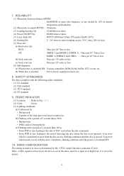
DRIVE CONFIGURATION The setting to the host is under way. (b) Flashing with a period of detecting the disc (when the disc is being played (c) Flashing with the following safety standards: (1) UL standard (2) CSA standard (3) TÜV standard (4) CE standard 9. SAFETY STANDARDS The drive complies with a period of 1 second (Duty 50%) • From POR or tray loading to the end of TOC read (when the disc is present) • From POR or tray loading to the end of 3 second (Duty 50%) • During write • While audio is not present). If an error which seems to the master....
DRIVE CONFIGURATION The setting to the host is under way. (b) Flashing with a period of detecting the disc (when the disc is being played (c) Flashing with the following safety standards: (1) UL standard (2) CSA standard (3) TÜV standard (4) CE standard 9. SAFETY STANDARDS The drive complies with a period of 1 second (Duty 50%) • From POR or tray loading to the end of TOC read (when the disc is present) • From POR or tray loading to the end of 3 second (Duty 50%) • During write • While audio is not present). If an error which seems to the master....
Hardware Specification
Page 12
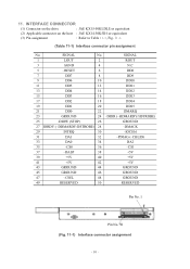
SIGNAL No. SIGNAL 1 LOUT 2 ROUT 3 AGND 4 N.C 5 -RESET 6 DD8 7 DD7 8 DD9 9 DD6 10 DD10 11 DD5 12 DD11 13 DD4 14 DD12 15 DD3 16 DD13 17 DD2 18 DD14 19 DD1 20 DD15 21 DD0 22 DMARQ 23 GROUND 24 -DIOR (-HDMARDY/HSTROBE) 25 -DIOW (STOP) 26 GROUND 27 IORDY (-DDMARDY/DSTROBE) 28 -DMACK 29 INTRQ 30 -IOCS16 31 DA1 32 -PDIAG (-CBLID) 33 DA0 34 DA2 35 -CS0 36 -CS1 37 -DASP 38 +5V 39 +5V 40 +5V 41 +5V 42 +5V 43 GROUND 44 GROUND 45 GROUND 46 GROUND 47 -CSEL 48 GROUND 49 RESERVED 50 RESERVED Pin No. 1 ...
SIGNAL No. SIGNAL 1 LOUT 2 ROUT 3 AGND 4 N.C 5 -RESET 6 DD8 7 DD7 8 DD9 9 DD6 10 DD10 11 DD5 12 DD11 13 DD4 14 DD12 15 DD3 16 DD13 17 DD2 18 DD14 19 DD1 20 DD15 21 DD0 22 DMARQ 23 GROUND 24 -DIOR (-HDMARDY/HSTROBE) 25 -DIOW (STOP) 26 GROUND 27 IORDY (-DDMARDY/DSTROBE) 28 -DMACK 29 INTRQ 30 -IOCS16 31 DA1 32 -PDIAG (-CBLID) 33 DA0 34 DA2 35 -CS0 36 -CS1 37 -DASP 38 +5V 39 +5V 40 +5V 41 +5V 42 +5V 43 GROUND 44 GROUND 45 GROUND 46 GROUND 47 -CSEL 48 GROUND 49 RESERVED 50 RESERVED Pin No. 1 ...
Hardware Specification
Page 13
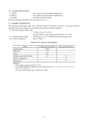
POWER MANAGEMENT SPECIFICATION". 3. 12. AUDIO INTERFACE (1) LOUT : Line output of the left channel (unbalanced) (2) ROUT : Line output of the right channel (unbalanced) (3) AGND : Ground of the line output, refer to "15. For each of the drive. The power should be supplied from a power supply unit with reinforced insulation or double insulation. (1) Allowable supply voltage range : +5VDC ±5% (4.75 to 5.25V) There should be no abnormal operations by DC +5V ±10%. (2) Allowable ripple voltage : 100mVp-p or less, 50 to 20MHz (including the spike noise) (3) Current ...
POWER MANAGEMENT SPECIFICATION". 3. 12. AUDIO INTERFACE (1) LOUT : Line output of the left channel (unbalanced) (2) ROUT : Line output of the right channel (unbalanced) (3) AGND : Ground of the line output, refer to "15. For each of the drive. The power should be supplied from a power supply unit with reinforced insulation or double insulation. (1) Allowable supply voltage range : +5VDC ±5% (4.75 to 5.25V) There should be no abnormal operations by DC +5V ±10%. (2) Allowable ripple voltage : 100mVp-p or less, 50 to 20MHz (including the spike noise) (3) Current ...
Hardware Specification
Page 14
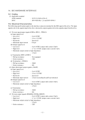
IDE HARDWARE INTERFACE 14.1 Outline (1) Applicable standard ANSI standard SFFC : X3T13/1321D (ATA-5) : SFF-8020i Rev. 2.6 and SFF-8090v3 14.2 Electrical Characteristics The following specifications apply to 3.3VDC (output source current 1mA) • Maximum output current at high impedance : ±25µA (c) Termination • Pull-up resistance) (b) Output signal level • Low level : 0 to 0.4VDC (output sink current 12mA) • Maximum output current at high impedance : ±25µA • Series resistance : 22Ω - 12 - The input signals refer to the ...
IDE HARDWARE INTERFACE 14.1 Outline (1) Applicable standard ANSI standard SFFC : X3T13/1321D (ATA-5) : SFF-8020i Rev. 2.6 and SFF-8090v3 14.2 Electrical Characteristics The following specifications apply to 3.3VDC (output source current 1mA) • Maximum output current at high impedance : ±25µA (c) Termination • Pull-up resistance) (b) Output signal level • Low level : 0 to 0.4VDC (output sink current 12mA) • Maximum output current at high impedance : ±25µA • Series resistance : 22Ω - 12 - The input signals refer to the ...
Hardware Specification
Page 15
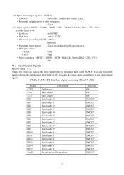
Among the following signals, the input signal refers to the signal input to the CD-RW drive and the output signal refers to the signal output from the CD-RW drive and the input/output signal refers to Table 14.3-1. (4) Open-drain output signals ( -IOCS16) • Low level : 0 to 0.4VDC (output sink current 12mA) • Maximum output current at high impedance : ±25µA (5) Input signals (-RESET, -DIOW, -DIOR, -CSEL, -DMACK, DA0 to DA2, -CS0, -CS1) (a) Input signal level • Low level : 0 to 0.8VDC • High level : 2.0 to 5.25VDC • Hysteresis (excluding ...
Among the following signals, the input signal refers to the signal input to the CD-RW drive and the output signal refers to the signal output from the CD-RW drive and the input/output signal refers to Table 14.3-1. (4) Open-drain output signals ( -IOCS16) • Low level : 0 to 0.4VDC (output sink current 12mA) • Maximum output current at high impedance : ±25µA (5) Input signals (-RESET, -DIOW, -DIOR, -CSEL, -DMACK, DA0 to DA2, -CS0, -CS1) (a) Input signal level • Low level : 0 to 0.8VDC • High level : 2.0 to 5.25VDC • Hysteresis (excluding ...
Hardware Specification
Page 16
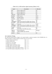
In timing description, H indicates high level (false) and L low level (true). (1) Reset timing (master/slave) : Fig. 14.4-1 (2) Reset timing (slave) : Fig. 14.4-2 (3) PIO write cycle timing : Fig. 14.4-3 (4) PIO read IN -HDMARDY DMA ready during Ultra DMA data in bursts IN HSTROBE Data strobe during Ultra DMA data out bursts IN IORDY I /O write IN STOP Stop during Ultra DMA data in burst) : Fig. 14.4-7 (8) Ultra DMA transfer timing (Data out burst) : Fig. 14.4-8 - 14 - (Table 14.3-1) IDE Interface signal summary (Sheet 2 of 2) Signal DA0 DA1 DA2 -DMACK DMARQ INTRQ -IOCS16...
In timing description, H indicates high level (false) and L low level (true). (1) Reset timing (master/slave) : Fig. 14.4-1 (2) Reset timing (slave) : Fig. 14.4-2 (3) PIO write cycle timing : Fig. 14.4-3 (4) PIO read IN -HDMARDY DMA ready during Ultra DMA data in bursts IN HSTROBE Data strobe during Ultra DMA data out bursts IN IORDY I /O write IN STOP Stop during Ultra DMA data in burst) : Fig. 14.4-7 (8) Ultra DMA transfer timing (Data out burst) : Fig. 14.4-8 - 14 - (Table 14.3-1) IDE Interface signal summary (Sheet 2 of 2) Signal DA0 DA1 DA2 -DMACK DMARQ INTRQ -IOCS16...
Hardware Specification
Page 17
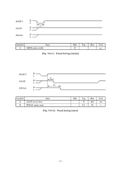
-RESET H L t1 -DASP H L -PDIAG H L Symbol Item t1 -HRST pulse width Min Typ Max Unit 25 µs (Fig. 14.4-1) Reset timing (master) -RESET H L -DASP H L -PDIAG H L t2 t4 Symbol Item t2 -DASP assert time t4 -PDIAG assert start Min Typ Max Unit 70 400 ms 0.2 30 s (Fig. 14.4-2) Reset timing (slave) - 15 -
-RESET H L t1 -DASP H L -PDIAG H L Symbol Item t1 -HRST pulse width Min Typ Max Unit 25 µs (Fig. 14.4-1) Reset timing (master) -RESET H L -DASP H L -PDIAG H L t2 t4 Symbol Item t2 -DASP assert time t4 -PDIAG assert start Min Typ Max Unit 70 400 ms 0.2 30 s (Fig. 14.4-2) Reset timing (slave) - 15 -
Hardware Specification
Page 18
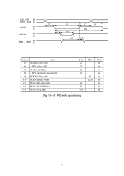
-CS0, CS1 H DA0 ~ DA2 L -DIOW H L IORDY H L DD0 ~ DD15 H L t5 t9 t6 t10 t11 t7 t8 t14 t12 Symbol Item t5 Address setup time t6 -IOW pulse width t7 Address hold time t8 -IOW interactive pulse width t9 IORDY delay time t10 IORDY pulse width t11 Write data setup time t12 Write data hold time t14 Write cycle time Min Max Unit 25 ns 70 ns 10 ns 25 ns 35 ns 1,250 ns 20 ns 10 ns 120 ns (Fig. 14.4-3) PIO write cycle timing - 16 -
-CS0, CS1 H DA0 ~ DA2 L -DIOW H L IORDY H L DD0 ~ DD15 H L t5 t9 t6 t10 t11 t7 t8 t14 t12 Symbol Item t5 Address setup time t6 -IOW pulse width t7 Address hold time t8 -IOW interactive pulse width t9 IORDY delay time t10 IORDY pulse width t11 Write data setup time t12 Write data hold time t14 Write cycle time Min Max Unit 25 ns 70 ns 10 ns 25 ns 35 ns 1,250 ns 20 ns 10 ns 120 ns (Fig. 14.4-3) PIO write cycle timing - 16 -
Hardware Specification
Page 19
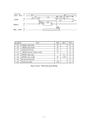
-CS0, CS1 H DA0 ~ DA2 L -DIOR H L IORDY H L DD0 ~ DD15 H L t15 t16 t19 t20 t17 t18 t24 t22 Symbol Item t15 Address setup time t16 -DIOR pulse width t17 Address hold time t18 -DIOR interactive pulse width t19 IORDY delay time t20 IORDY pulse width t22 Read data hold time t24 Read cycle time Min Max Unit 25 ns 70 ns 10 ns 25 ns 35 ns 90 1,250 ns 5 ns 120 ns (Fig. 14.4-4) PIO read cycle timing - 17 -
-CS0, CS1 H DA0 ~ DA2 L -DIOR H L IORDY H L DD0 ~ DD15 H L t15 t16 t19 t20 t17 t18 t24 t22 Symbol Item t15 Address setup time t16 -DIOR pulse width t17 Address hold time t18 -DIOR interactive pulse width t19 IORDY delay time t20 IORDY pulse width t22 Read data hold time t24 Read cycle time Min Max Unit 25 ns 70 ns 10 ns 25 ns 35 ns 90 1,250 ns 5 ns 120 ns (Fig. 14.4-4) PIO read cycle timing - 17 -