DW-224E-V Brochure
Page 1
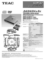
... ) MS 4x(CLV) Read Speed DVD-ROM 8x ( CAV) DVD-Video *' 4x ( CAV) DVD±R 8x ( CAV) DVD±RW 8x ( CAV) DVD±R DL ( Finalized Disc ) 8x ( CAV) DVD-RAM ( 4.7GB ) 5x ( CAV) CD-ROM 24x ( CAV ) CD-R 24x ( CAV ) CD-RW 24x ( CAV ) CD-DA ( DAE ) 20x ( CAV ) Play Audio *1 4x ( CLV) Video CD *1 20x ( CAV ) Disc Diameter 12cm , 8cm Interface ATA/ATAPI ( IDE ) Serial ATA (SATA) Data Transfer Rate Programmed...
... ) MS 4x(CLV) Read Speed DVD-ROM 8x ( CAV) DVD-Video *' 4x ( CAV) DVD±R 8x ( CAV) DVD±RW 8x ( CAV) DVD±R DL ( Finalized Disc ) 8x ( CAV) DVD-RAM ( 4.7GB ) 5x ( CAV) CD-ROM 24x ( CAV ) CD-R 24x ( CAV ) CD-RW 24x ( CAV ) CD-DA ( DAE ) 20x ( CAV ) Play Audio *1 4x ( CLV) Video CD *1 20x ( CAV ) Disc Diameter 12cm , 8cm Interface ATA/ATAPI ( IDE ) Serial ATA (SATA) Data Transfer Rate Programmed...
Hardware Specification
Page 1
A 34 sheets in Total 7757a TEAC DW-224E-R93 CD-RW/DVD-ROM DRIVE HARDWARE SPECIFICATION Rev.
A 34 sheets in Total 7757a TEAC DW-224E-R93 CD-RW/DVD-ROM DRIVE HARDWARE SPECIFICATION Rev.
Hardware Specification
Page 2
....5.1 Tray ejection/insertion in the sleep mode 31 16. OTHERS ...31 16.1 Using the lens cleaner ...31 16.2 Safety of Laser Products 32 - i - CONSTRUCTION ...2 3.1 External Construction ...2 3.2 Installation ...4 4. PERFORMANCE ...7 5.1 Operating Performance ...7 5.2 Audio ...7 5.3 Acoustic Noise ...7 6. DRIVE CONFIGURATION ...9 11. INTERFACE CONNECTOR ...10 12. DISC SPECIFICATION ...5 4.1 Applicable Disc Format ...5 4.2 Rotational Speed ...5 4.3 Data Capacity ...6 4.4 Write methods ...6 4.5 Readable disc ...6 4.6 Recordable Disc (Recording Speed 6 5. POWER INTERFACE...
....5.1 Tray ejection/insertion in the sleep mode 31 16. OTHERS ...31 16.1 Using the lens cleaner ...31 16.2 Safety of Laser Products 32 - i - CONSTRUCTION ...2 3.1 External Construction ...2 3.2 Installation ...4 4. PERFORMANCE ...7 5.1 Operating Performance ...7 5.2 Audio ...7 5.3 Acoustic Noise ...7 6. DRIVE CONFIGURATION ...9 11. INTERFACE CONNECTOR ...10 12. DISC SPECIFICATION ...5 4.1 Applicable Disc Format ...5 4.2 Rotational Speed ...5 4.3 Data Capacity ...6 4.4 Write methods ...6 4.5 Readable disc ...6 4.6 Recordable Disc (Recording Speed 6 5. POWER INTERFACE...
Hardware Specification
Page 3
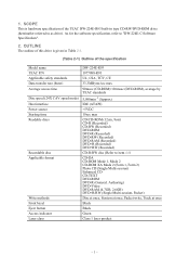
... of this drive is hardware specification of the specification Model name TEAC P/N Applicable safety standards Data transfer rate (burst) Average access time Disc speed (24X CAV speed mode) Host interface Power source Starting time Readable discs Recordable disc Applicable format Write methods Front bezel Eject button Access indicator Laser class DW-224E-R93 1977098-R93 UL, CSA, TÜV, CE 33.3MBytes/sec max 90msec (CD-ROM)/110msec (DVD-ROM), average by TEAC standards 5,090min-1 (Approx) IDE (ATAPI) +5VDC...
... of this drive is hardware specification of the specification Model name TEAC P/N Applicable safety standards Data transfer rate (burst) Average access time Disc speed (24X CAV speed mode) Host interface Power source Starting time Readable discs Recordable disc Applicable format Write methods Front bezel Eject button Access indicator Laser class DW-224E-R93 1977098-R93 UL, CSA, TÜV, CE 33.3MBytes/sec max 90msec (CD-ROM)/110msec (DVD-ROM), average by TEAC standards 5,090min-1 (Approx) IDE (ATAPI) +5VDC...
Hardware Specification
Page 4
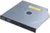
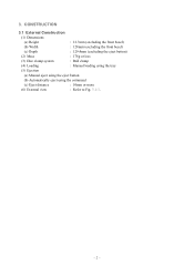
CONSTRUCTION 3.1 External Construction (1) Dimensions (a) Height : 12.7mm (excluding the front bezel) (b) Width : 128mm (excluding the front bezel) (c) Depth : 129.4mm (excluding the eject button) (2) Mass : 178g or less (3) Disc clamp system : Ball clamp (4) Loading : Manual loading using the tray (5) Ejection (a) Manual eject using the eject button (b) Automatically eject using the command (c) Eject distance : 10mm or more (6) External view : Refer to Fig. 3.1-1. - 2 - 3.
CONSTRUCTION 3.1 External Construction (1) Dimensions (a) Height : 12.7mm (excluding the front bezel) (b) Width : 128mm (excluding the front bezel) (c) Depth : 129.4mm (excluding the eject button) (2) Mass : 178g or less (3) Disc clamp system : Ball clamp (4) Loading : Manual loading using the tray (5) Ejection (a) Manual eject using the eject button (b) Automatically eject using the command (c) Eject distance : 10mm or more (6) External view : Refer to Fig. 3.1-1. - 2 - 3.
Hardware Specification
Page 6
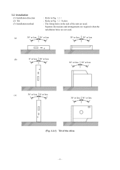
3.2 Installation (1) Installation direction (2) Tilt (3) Installation method : Refer to Fig. 3.2-1 : Refer to Fig. 3.2-1 below. : The fixing holes in the side of the unit are not used . Separate discussions and arrangements are required when the installation holes are used . (a) 30° or less 30° or less 30° or less 30° or less (b) 0° or less 30° or less 30° or less 30° or less (c) 30° or less 0° or less 30° or less 30° or less (Fig. 3.2-1) Tilt of the drive - 4 -
3.2 Installation (1) Installation direction (2) Tilt (3) Installation method : Refer to Fig. 3.2-1 : Refer to Fig. 3.2-1 below. : The fixing holes in the side of the unit are not used . Separate discussions and arrangements are required when the installation holes are used . (a) 30° or less 30° or less 30° or less 30° or less (b) 0° or less 30° or less 30° or less 30° or less (c) 30° or less 0° or less 30° or less 30° or less (Fig. 3.2-1) Tilt of the drive - 4 -
Hardware Specification
Page 7
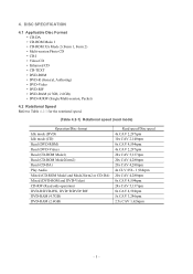
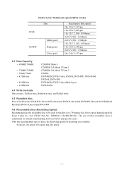
... DVD-ROM • DVD-R (General, Authoring) • DVD-Video • DVD-RW • DVD-RAM (4.7GB, 2.6GB) • DVD+R/RW (Single/Multi-session, Packet) 4.2 Rotational Speed Refer to Table 4.2-1 for the rotational speed. (Table 4.2-1) Rotational speed (read mode) Operation/Disc format Idle mode (DVD) Idle mode (CD) Read (DVD-ROM) Read (DVD-Video) Read (CD-ROM Model) Read (CD-ROM Mode2form2) Read (CD-DA) Play Audio Mixed (CD-ROM Model and Mode2form2 or CD-DA) Mixed (DVD-ROM and DVD-Video) CD-RW (Read only operation) DVD-R/DVD-RW, DVD+R/DVD+RW DVD-RAM (4.7GB) DVD-RAM (2.6GB) Read speed/Disc...
... DVD-ROM • DVD-R (General, Authoring) • DVD-Video • DVD-RW • DVD-RAM (4.7GB, 2.6GB) • DVD+R/RW (Single/Multi-session, Packet) 4.2 Rotational Speed Refer to Table 4.2-1 for the rotational speed. (Table 4.2-1) Rotational speed (read mode) Operation/Disc format Idle mode (DVD) Idle mode (CD) Read (DVD-ROM) Read (DVD-Video) Read (CD-ROM Model) Read (CD-ROM Mode2form2) Read (CD-DA) Play Audio Mixed (CD-ROM Model and Mode2form2 or CD-DA) Mixed (DVD-ROM and DVD-Video) CD-RW (Read only operation) DVD-R/DVD-RW, DVD+R/DVD+RW DVD-RAM (4.7GB) DVD-RAM (2.6GB) Read speed/Disc...
Hardware Specification
Page 8
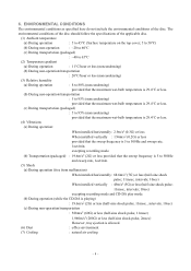
...CD-DA : DVD-ROM, DVD-Video, DVD-R, DVD-RW, DVD-RAM, DVD+R, DVD+RW : DVD-ROM, DVD-Video (Dual layer) : DVD-RAM 4.4 Write methods Disc at once, Track at once, Session at once, and Packet write 4.5 Readable disc Press CD, Recorded CD-R/RW, Press DVD, Recorded DVD-R, Recorded DVD-RW, Recorded DVD-RAM, Recorded DVD+R, Recorded DVD+RW 4.6 Recordable Disc (Recording Speed) Recommended as the recordable disc to be used in this drive is conditional on mutual understanding between TEAC and specific users. The use of recording are available: 4x speed, 10x speed, 16x speed and 24x speed - 6 - With...
...CD-DA : DVD-ROM, DVD-Video, DVD-R, DVD-RW, DVD-RAM, DVD+R, DVD+RW : DVD-ROM, DVD-Video (Dual layer) : DVD-RAM 4.4 Write methods Disc at once, Track at once, Session at once, and Packet write 4.5 Readable disc Press CD, Recorded CD-R/RW, Press DVD, Recorded DVD-R, Recorded DVD-RW, Recorded DVD-RAM, Recorded DVD+R, Recorded DVD+RW 4.6 Recordable Disc (Recording Speed) Recommended as the recordable disc to be used in this drive is conditional on mutual understanding between TEAC and specific users. The use of recording are available: 4x speed, 10x speed, 16x speed and 24x speed - 6 - With...
Hardware Specification
Page 9
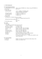
... (1) Operating (2) Ejecting : 45dBA or less (during seek/read/write/Active/Idle, distance 0.5m) : 65dBA or less (distance 0.5m) - 7 - PERFORMANCE 5.1 Operating Performance (1) Average random access time : 90msec average (CD-ROM, 24x), 110msec average (DVD-ROM, 8x) (2) Disc speed : Refer to 4.2 (3) Data transfer rate (a) Read sustained : 1,545 to 3,600kB/sec (CD-ROM model) 4,469 to 10,816kB/sec (DVD-ROM) (b) Programmed I/O : 16.7MB/sec max (Mode 0 to 4) (c) Multi-word...
... (1) Operating (2) Ejecting : 45dBA or less (during seek/read/write/Active/Idle, distance 0.5m) : 65dBA or less (distance 0.5m) - 7 - PERFORMANCE 5.1 Operating Performance (1) Average random access time : 90msec average (CD-ROM, 24x), 110msec average (DVD-ROM, 8x) (2) Disc speed : Refer to 4.2 (3) Data transfer rate (a) Read sustained : 1,545 to 3,600kB/sec (CD-ROM model) 4,469 to 10,816kB/sec (DVD-ROM) (b) Programmed I/O : 16.7MB/sec max (Mode 0 to 4) (c) Multi-word...
Hardware Specification
Page 10
.../min. (5) Shock (a) During operation (free from malfunction) When installed horizontally: 68.6m/s2 (7G) or less (half-sine shock pulse; 11msec, intervals; 10sec) When installed vertically : 49m/s2 (5G) or less (half-sine shock pulse; 11msec, intervals; 10sec) excepting recording mode and CD-DA play mode. (b) During operation (while the CD-DA is playing) : 19.6m/s2 (2G...
.../min. (5) Shock (a) During operation (free from malfunction) When installed horizontally: 68.6m/s2 (7G) or less (half-sine shock pulse; 11msec, intervals; 10sec) When installed vertically : 49m/s2 (5G) or less (half-sine shock pulse; 11msec, intervals; 10sec) excepting recording mode and CD-DA play mode. (b) During operation (while the CD-DA is playing) : 19.6m/s2 (2G...
Hardware Specification
Page 11
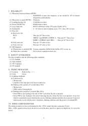
... per 109 bits or less (b) Seek error rate : Once per 106 seeks or less (c) Seek error rate : Once per 106 seeks or less (8) Self-diagnosis (a) When power is switched ON: Various controllers, ROM, RAM, buffer, ECC circuit, etc. (b) When disc is determined by the −CSEL signal (interface connector 47 pin). If an error which is considered to master or slave is...
... per 109 bits or less (b) Seek error rate : Once per 106 seeks or less (c) Seek error rate : Once per 106 seeks or less (8) Self-diagnosis (a) When power is switched ON: Various controllers, ROM, RAM, buffer, ECC circuit, etc. (b) When disc is determined by the −CSEL signal (interface connector 47 pin). If an error which is considered to master or slave is...
Hardware Specification
Page 13
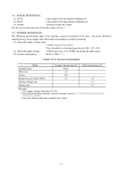
... Mode Standby/Sleep Write 24x Average current max (A) 0.025 1.0 Peak current max (A) Active 0.9 Random access (Duty 100%) 1.2 1.5 During starting/seek 1.5 During eject 1.5 Remarks: 1. Does not include pulse-like current below 1msec. - 11 - POWER MANAGEMENT SPECIFICATION". 3. For the electrical specification of the line output, refer to the interface connector terminals of audio line output. POWER INTERFACE The following specifications apply to...
... Mode Standby/Sleep Write 24x Average current max (A) 0.025 1.0 Peak current max (A) Active 0.9 Random access (Duty 100%) 1.2 1.5 During starting/seek 1.5 During eject 1.5 Remarks: 1. Does not include pulse-like current below 1msec. - 11 - POWER MANAGEMENT SPECIFICATION". 3. For the electrical specification of the line output, refer to the interface connector terminals of audio line output. POWER INTERFACE The following specifications apply to...
Hardware Specification
Page 14
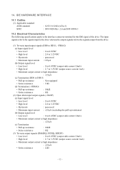
...• Series resistance : 33Ω (d) Termination (-PDIAG) • Pull-up resistance : 10kΩ • Series resistance : 0Ω (2) Open drain input/output signals (-DASP) (a) Input signal level • Low level : 0 to 0.8VDC • High level : 2.0 to 5.25VDC •... : 2.7 to the interface connector terminal for the IDE signal of the drive. IDE HARDWARE INTERFACE 14.1 Outline (1) Applicable standard ANSI standard SFFC : X3T13/1321D (ATA-5) : SFF-8020i Rev. 2.6 and SFF-8090v3 14.2 Electrical Characteristics The following specifications apply to 3.3VDC (output ...
...• Series resistance : 33Ω (d) Termination (-PDIAG) • Pull-up resistance : 10kΩ • Series resistance : 0Ω (2) Open drain input/output signals (-DASP) (a) Input signal level • Low level : 0 to 0.8VDC • High level : 2.0 to 5.25VDC •... : 2.7 to the interface connector terminal for the IDE signal of the drive. IDE HARDWARE INTERFACE 14.1 Outline (1) Applicable standard ANSI standard SFFC : X3T13/1321D (ATA-5) : SFF-8020i Rev. 2.6 and SFF-8090v3 14.2 Electrical Characteristics The following specifications apply to 3.3VDC (output ...
Hardware Specification
Page 15
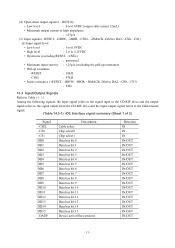
... DD7 DD8 DD9 DD10 DD11 DD12 DD13 DD14 DD15 -DASP Description Cable select Chip select0 Chip select1 Data bus bit 0 Data bus bit 1 Data bus bit 2 Data bus bit 3 Data bus bit 4 Data bus bit 5 Data bus bit 6 Data bus bit 7 Data bus bit 8 Data bus bit 9 Data bus bit 10 Data bus bit 11 Data bus bit 12 Data bus bit 13 Data bus bit 14 Data bus bit 15 Device active/Slave present Direction IN IN IN IN/OUT IN/OUT IN/OUT IN/OUT...
... DD7 DD8 DD9 DD10 DD11 DD12 DD13 DD14 DD15 -DASP Description Cable select Chip select0 Chip select1 Data bus bit 0 Data bus bit 1 Data bus bit 2 Data bus bit 3 Data bus bit 4 Data bus bit 5 Data bus bit 6 Data bus bit 7 Data bus bit 8 Data bus bit 9 Data bus bit 10 Data bus bit 11 Data bus bit 12 Data bus bit 13 Data bus bit 14 Data bus bit 15 Device active/Slave present Direction IN IN IN IN/OUT IN/OUT IN/OUT IN/OUT...
Hardware Specification
Page 16
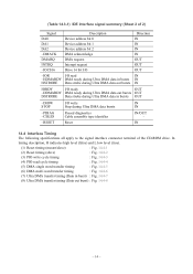
... Cable assembly type identifier IN/OUT - -RESET Reset IN 14.4 Interface Timing The following specifications all apply to the signal interface connector terminal of the CD-ROM drive. In timing description, H indicates high level (false) and L low level (true). (1) Reset timing (master/slave) : Fig. 14.4-1 (2) Reset timing (slave) : Fig. 14.4-2 (3) PIO write cycle timing : Fig. 14.4-3 (4) PIO read IN -HDMARDY DMA ready during Ultra DMA data...
... Cable assembly type identifier IN/OUT - -RESET Reset IN 14.4 Interface Timing The following specifications all apply to the signal interface connector terminal of the CD-ROM drive. In timing description, H indicates high level (false) and L low level (true). (1) Reset timing (master/slave) : Fig. 14.4-1 (2) Reset timing (slave) : Fig. 14.4-2 (3) PIO write cycle timing : Fig. 14.4-3 (4) PIO read IN -HDMARDY DMA ready during Ultra DMA data...
Hardware Specification
Page 29
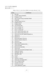
.../RESUME PLAY AUDIO (10) PLAY AUDIO (12) PLAY AUDIO MSF PLAY TRACK RELATIVE (10) PLAY TRACK RELATIVE (12) PREVENT/ALLOW MEDIUM REMOVAL READ (10) READ (12) READ BUFFER CAPACITY READ CD/DVD CAPACITY READ CD READ CD MSF READ DISC INFORMATION READ HEADER READ SUB-CHANNEL READ TOC READ TRACK/RZONE INFORMATION REQUEST SENSE RESERVE TRACK REZERO UNIT SCAN SEEK SEND CUE SHEET SEND OPC INFORMATION SET CD-ROM SPEED START/STOP UNIT STOP PLAY/SCAN...
.../RESUME PLAY AUDIO (10) PLAY AUDIO (12) PLAY AUDIO MSF PLAY TRACK RELATIVE (10) PLAY TRACK RELATIVE (12) PREVENT/ALLOW MEDIUM REMOVAL READ (10) READ (12) READ BUFFER CAPACITY READ CD/DVD CAPACITY READ CD READ CD MSF READ DISC INFORMATION READ HEADER READ SUB-CHANNEL READ TOC READ TRACK/RZONE INFORMATION REQUEST SENSE RESERVE TRACK REZERO UNIT SCAN SEEK SEND CUE SHEET SEND OPC INFORMATION SET CD-ROM SPEED START/STOP UNIT STOP PLAY/SCAN...
Hardware Specification
Page 30
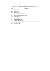
(Table 14.5.2-1) List of the ATAPI commands (Sheet 2 of 2) CODE 00 2A AA AD 23 A4 A3 A7 46 AC A2 COMMAND TEST UNIT READY WRITE (10) WRITE (12) READ DVD STRUCTURE READ FORMATTED CAPACITIES REPORT KEY SEND KEY SET READ AHEAD GET CONFIGURATION GET PERFORMANCE SEND EVENT - 28 -
(Table 14.5.2-1) List of the ATAPI commands (Sheet 2 of 2) CODE 00 2A AA AD 23 A4 A3 A7 46 AC A2 COMMAND TEST UNIT READY WRITE (10) WRITE (12) READ DVD STRUCTURE READ FORMATTED CAPACITIES REPORT KEY SEND KEY SET READ AHEAD GET CONFIGURATION GET PERFORMANCE SEND EVENT - 28 -
Hardware Specification
Page 32
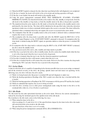
...power is switched ON and self diagnosis is under way. (2) While the booting operation or Reading of the TOC is under way or when a command which requires disc access is executed. (7) The resumption after the sleep mode is possible only after the RESET signal, the SRST (bit 2 of the DEVICE Control Register) or the ATAPI SOFT RESET... to the active mode is initiated when a command which requires disc access is set to 8 seconds. (2) When using the SRST or the ATAPI SOFT RESET command, the drive enters the standby mode. (9) Tray ejection in each of the active, idle, standby and sleep modes is...
...power is switched ON and self diagnosis is under way. (2) While the booting operation or Reading of the TOC is under way or when a command which requires disc access is executed. (7) The resumption after the sleep mode is possible only after the RESET signal, the SRST (bit 2 of the DEVICE Control Register) or the ATAPI SOFT RESET... to the active mode is initiated when a command which requires disc access is set to 8 seconds. (2) When using the SRST or the ATAPI SOFT RESET command, the drive enters the standby mode. (9) Tray ejection in each of the active, idle, standby and sleep modes is...
Hardware Specification
Page 33
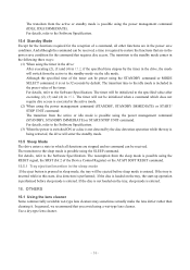
... start-up operation is performed before sleep mode is executed in 15.2. OTHERS 16.1 Using the lens cleaner Some commercially available wet-type lens cleaners may sometimes actually make the lens dirtier rather than cleaning it is performed; The transition time to the idle mode is included in this state, disc detection is set to the Software Specification. (3) When the power...
... start-up operation is performed before sleep mode is executed in 15.2. OTHERS 16.1 Using the lens cleaner Some commercially available wet-type lens cleaners may sometimes actually make the lens dirtier rather than cleaning it is performed; The transition time to the idle mode is included in this state, disc detection is set to the Software Specification. (3) When the power...
Hardware Specification
Page 34
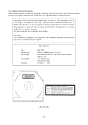
... procedures other than 1.4mW (Play) and 75mW (Record) on which the following text is printed with this regulation is shown bellow. This product has been designed and manufactured according to an end user, print the following text in hazardous radiation exposure. Type Manufacturer Laser output Wavelength Standard Optical pickup : HOP-6201T : Hitachi Media Electronics Co., Ltd. : Less...
... procedures other than 1.4mW (Play) and 75mW (Record) on which the following text is printed with this regulation is shown bellow. This product has been designed and manufactured according to an end user, print the following text in hazardous radiation exposure. Type Manufacturer Laser output Wavelength Standard Optical pickup : HOP-6201T : Hitachi Media Electronics Co., Ltd. : Less...


