Service Manual
Page 1
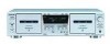
SERVICE MANUAL Ver 1.0 2001.04 TC-WE475 US Model Canadian Model AEP Model UK Model E Model Australian Model Dolby noise reduction extension manufactured under license from Dolby Laboratories Licensing Corporation. STEREO CASSETTE DECK 9-873-893-11 2001D0900-1 © 2001. 4 Sony Corporation Home Audio Company Shinagawa Tec Service Manual Production Group and "HX PRO" are trademarks of...
SERVICE MANUAL Ver 1.0 2001.04 TC-WE475 US Model Canadian Model AEP Model UK Model E Model Australian Model Dolby noise reduction extension manufactured under license from Dolby Laboratories Licensing Corporation. STEREO CASSETTE DECK 9-873-893-11 2001D0900-1 © 2001. 4 Sony Corporation Home Audio Company Shinagawa Tec Service Manual Production Group and "HX PRO" are trademarks of...
Service Manual
Page 2
... Fig. A battery-operated AC milliammeter. The Simpson 250 and Sanwa SH-63Trd are examples of three methods. 1. Using an AC voltmeter to change without notice. TC-WE475 General Power requirements U.S.A.and Canadian models: 120 V AC, 60Hz European models: 230 V AC, 50/60Hz Australian models: 240 V AC, 50/60Hz Other models: 120/... LES NUMÉROS SONT DONNÉS DANS CE MANUEL OU DANS LES SUPPLÉMENTS PUBLIÉS PAR SONY. 2 SAFETY CHECK-OUT After correcting the original service problem, perform the following safety checks before releasing the set to chassis, must have a 2V AC ...
... Fig. A battery-operated AC milliammeter. The Simpson 250 and Sanwa SH-63Trd are examples of three methods. 1. Using an AC voltmeter to change without notice. TC-WE475 General Power requirements U.S.A.and Canadian models: 120 V AC, 60Hz European models: 230 V AC, 50/60Hz Australian models: 240 V AC, 50/60Hz Other models: 120/... LES NUMÉROS SONT DONNÉS DANS CE MANUEL OU DANS LES SUPPLÉMENTS PUBLIÉS PAR SONY. 2 SAFETY CHECK-OUT After correcting the original service problem, perform the following safety checks before releasing the set to chassis, must have a 2V AC ...
Service Manual
Page 3
... model AEP model UK model SP model AUS model • Abbreviation CND : Canadian model SP : Singapore model AUS : Australian model TC-WE475 TABLE OF CONTENTS 1. GENERAL 4 2. DISASSEMBLY 2-1. Front Panel Assy 5 2-3. Cassette Lid Assy (Deck A/B 6 2-4. Circuit Boards Location 12 6-2. Printed Wiring Board - MAIN (1/4) Section 15 6-4. MAIN (2/4) Section 16 6-5. Schematic Diagram - Printed Wiring Board - Printed Wiring...
... model AEP model UK model SP model AUS model • Abbreviation CND : Canadian model SP : Singapore model AUS : Australian model TC-WE475 TABLE OF CONTENTS 1. GENERAL 4 2. DISASSEMBLY 2-1. Front Panel Assy 5 2-3. Cassette Lid Assy (Deck A/B 6 2-4. Circuit Boards Location 12 6-2. Printed Wiring Board - MAIN (1/4) Section 15 6-4. MAIN (2/4) Section 16 6-5. Schematic Diagram - Printed Wiring Board - Printed Wiring...
Service Manual
Page 4
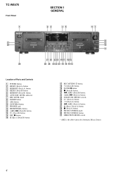
... 0 qa Location of Parts and Controls 1 POWER button 2 RESET (Deck A) button 3 MEMORY (Deck A) button 4 RESET (Deck B) button 5 MEMORY (Deck B) button 6 AUTO REC LEVEL indicator 7 REC LEVEL knob 8 FADER...Deck B) button ql PAUSE X button w; PITCH CONTROL button ea DIRECTION MODE switch • AMS is the abbreviation for Automatic Music Sensor. 4 x (Deck B) button wa m (AMS) (Deck B) button ws (AMS) M (Deck A) button wd DOLBY NR OFF B/C switch wf H (Deck A) button wg h (Deck A) button wh m (AMS) (Deck A) button wj A (Eject) (Deck A) button wk x (Deck A) button wl PITCH CONTROL knob e; TC-WE475...
... 0 qa Location of Parts and Controls 1 POWER button 2 RESET (Deck A) button 3 MEMORY (Deck A) button 4 RESET (Deck B) button 5 MEMORY (Deck B) button 6 AUTO REC LEVEL indicator 7 REC LEVEL knob 8 FADER...Deck B) button ql PAUSE X button w; PITCH CONTROL button ea DIRECTION MODE switch • AMS is the abbreviation for Automatic Music Sensor. 4 x (Deck B) button wa m (AMS) (Deck B) button ws (AMS) M (Deck A) button wd DOLBY NR OFF B/C switch wf H (Deck A) button wg h (Deck A) button wh m (AMS) (Deck A) button wj A (Eject) (Deck A) button wk x (Deck A) button wl PITCH CONTROL knob e; TC-WE475...
Service Manual
Page 5
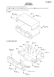
...equipment can be removed using the following procedure. CASE 3 two screws (case 3 TP2) 4 case TC-WE475 Mechanism Deck Assy (Deck A/B) 1 screw (BVTT 3x6) 2 two screws (case 3 TP2) 2-2. FRONT PANEL ASSY 2 CN807 5 flat type wire (Deck A) 8 CN301 9 CN002 qj claw 1 CN5802 3 CN803 4 CNA806 0 screw (BVTP 3x8) 7... qh claw qf screw (BVTP 3x8) 6 flat type wire (Deck B) qg two screws (BVTT 3x6) qd screw (BVTP 3x8) qk front panel assy qs screw (BVTP 3x8) 5 Set Case Front Panel Assy Cassette Lid Assy (Deck A/B) Note : Follow the disassembly procedure in the numerical order given...
...equipment can be removed using the following procedure. CASE 3 two screws (case 3 TP2) 4 case TC-WE475 Mechanism Deck Assy (Deck A/B) 1 screw (BVTT 3x6) 2 two screws (case 3 TP2) 2-2. FRONT PANEL ASSY 2 CN807 5 flat type wire (Deck A) 8 CN301 9 CN002 qj claw 1 CN5802 3 CN803 4 CNA806 0 screw (BVTP 3x8) 7... qh claw qf screw (BVTP 3x8) 6 flat type wire (Deck B) qg two screws (BVTT 3x6) qd screw (BVTP 3x8) qk front panel assy qs screw (BVTP 3x8) 5 Set Case Front Panel Assy Cassette Lid Assy (Deck A/B) Note : Follow the disassembly procedure in the numerical order given...
Service Manual
Page 6
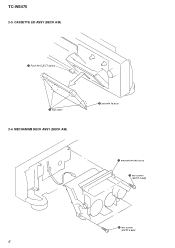
TC-WE475 2-3. CASSETTE LID ASSY (DECK A/B) 1 Push the EJECT button. 2 four claws 2-4. MECHANISM DECK ASSY (DECK A/B) 3 cassette lid assy 3 mechanism deck assy 1 two screws (BVTP 2.6x8) 2 two screws (BVTP 2.6x8) 6
TC-WE475 2-3. CASSETTE LID ASSY (DECK A/B) 1 Push the EJECT button. 2 four claws 2-4. MECHANISM DECK ASSY (DECK A/B) 3 cassette lid assy 3 mechanism deck assy 1 two screws (BVTP 2.6x8) 2 two screws (BVTP 2.6x8) 6

Service Manual
Page 7
... Display 0 1 2 3 4 Segment check display (*2) 5 6 7 8 9 A b All lit h PLAY H Grit check display (*1) RMS Segment check display (*2) 7 SECTION 3 SERVICE MODE TC-WE475 KEY CHECK & DISPLAY CHECK MODE While pressing the h (A deck) and REC MUTING W buttons with the power off, press the POWER button to the position of the switch. The fluorescent indicator tube displays the number...
... Display 0 1 2 3 4 Segment check display (*2) 5 6 7 8 9 A b All lit h PLAY H Grit check display (*1) RMS Segment check display (*2) 7 SECTION 3 SERVICE MODE TC-WE475 KEY CHECK & DISPLAY CHECK MODE While pressing the h (A deck) and REC MUTING W buttons with the power off, press the POWER button to the position of the switch. The fluorescent indicator tube displays the number...
Service Manual
Page 8
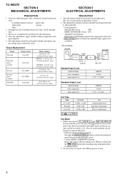
... • Counter RESET & MEMORY function Resets the counter when recording starts. When rewound with the power off, press the ! TC-WE475 SECTION 4 MECHANICAL ADJUSTMENTS PRECAUTION 1. Demagnetize the record/playback head with a denatured alcohol-moistened swab : record/playback/erase head pinch roller...315 Hz, 0 dB 0 dBs = 0.775 V Use Azimuth Adjustment Tape Speed Adjustment PB Level Adjustment Test Mode 1. While pressing the H (DECK A) and REC MUTING W buttons with the m (AMS) button after recording, stops at first.) 2. The test mode performs the following parts with a ...
... • Counter RESET & MEMORY function Resets the counter when recording starts. When rewound with the power off, press the ! TC-WE475 SECTION 4 MECHANICAL ADJUSTMENTS PRECAUTION 1. Demagnetize the record/playback head with a denatured alcohol-moistened swab : record/playback/erase head pinch roller...315 Hz, 0 dB 0 dBs = 0.775 V Use Azimuth Adjustment Tape Speed Adjustment PB Level Adjustment Test Mode 1. While pressing the H (DECK A) and REC MUTING W buttons with the m (AMS) button after recording, stops at first.) 2. The test mode performs the following parts with a ...
Service Manual
Page 9
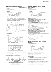
... Playback Level Adjustment Procedure: - Forward Playback Mode - record/playback head - quency counter reading becomes 3,000 ± 90 Hz. (Pitch control adjustment) (DECK A) 9. L-CH peak output within level 1 dB within 1 dB. Change the reverse playback mode and repeat the steps 1 to playback. 7. Press the... Pattern In phase 45˚ good 90˚ 135˚ 180˚ wrong 4. Adjust RV318 so that the fre- TC-WE475 Record/Playback Head Azimuth Adjustment DECK A Procedure: 1. quency counter reading becomes 5,980 ± 180 Hz. (Normal speed adjustment) 6. Forward Playback Mode -...
... Playback Level Adjustment Procedure: - Forward Playback Mode - record/playback head - quency counter reading becomes 3,000 ± 90 Hz. (Pitch control adjustment) (DECK A) 9. L-CH peak output within level 1 dB within 1 dB. Change the reverse playback mode and repeat the steps 1 to playback. 7. Press the... Pattern In phase 45˚ good 90˚ 135˚ 180˚ wrong 4. Adjust RV318 so that the fre- TC-WE475 Record/Playback Head Azimuth Adjustment DECK A Procedure: 1. quency counter reading becomes 5,980 ± 180 Hz. (Normal speed adjustment) 6. Forward Playback Mode -...

Service Manual
Page 10
... in step 2 become adjustment level as follows. Adjustment Value: Maximum 220 mV Adjustment Location: MAIN board (See page 14.) Record Bias Adjustment DECK B Setting: REC LEVEL knob : standard record position (See page 11.) Procedure: 1. Playback Mode recorded portion set 600 Ω LINE IN... then press the H button to repeat steps 3 and 4. Insert a tape into deck B, press the REC z button and then press the H button to repeat steps 3 and 4. TC-WE475 Bias Consumption Current Adjustment DECK B This adjustment should be performed when replacing the head assy or the bias oscillator ...
... in step 2 become adjustment level as follows. Adjustment Value: Maximum 220 mV Adjustment Location: MAIN board (See page 14.) Record Bias Adjustment DECK B Setting: REC LEVEL knob : standard record position (See page 11.) Procedure: 1. Playback Mode recorded portion set 600 Ω LINE IN... then press the H button to repeat steps 3 and 4. Insert a tape into deck B, press the REC z button and then press the H button to repeat steps 3 and 4. TC-WE475 Bias Consumption Current Adjustment DECK B This adjustment should be performed when replacing the head assy or the bias oscillator ...
Service Manual
Page 12
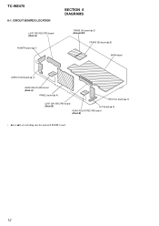
CIRCUIT BOARDS LOCATION LEAF SW (REC/PB) board (Deck A) POWER board (v F) SECTION 6 DIAGRAMS TRANS (A) board (v E) (Except SP) TRANS (B) board (v B) MAIN board DIRECTION board (v C) HEAD RELAY(PB) board (Deck A) PANEL board (v A) RECVOL board (v G) LEAF SW (REC/PB) board (Deck B) H.P board (v D) HEAD RELAY(REC/PB) board (Deck B) • vA to vG are including into the mounted PANEL board. 12 TC-WE475 6-1.
CIRCUIT BOARDS LOCATION LEAF SW (REC/PB) board (Deck A) POWER board (v F) SECTION 6 DIAGRAMS TRANS (A) board (v E) (Except SP) TRANS (B) board (v B) MAIN board DIRECTION board (v C) HEAD RELAY(PB) board (Deck A) PANEL board (v A) RECVOL board (v G) LEAF SW (REC/PB) board (Deck B) H.P board (v D) HEAD RELAY(REC/PB) board (Deck B) • vA to vG are including into the mounted PANEL board. 12 TC-WE475 6-1.
Service Manual
Page 13
d : PB G : REC (DECK B) • Abbreviation CND : Canadian model. no -signal (detuned) condition. Voltage variations may be noted due to normal produc- Voltage variations may be measured. • Voltages ... mark : STOP ( ) : REC < > : PB ∗ : Can not be noted due to normal produc- AUS : Australian model. MAIN SECTION (3/4) - 1 4.4Vp-p 10MHz IC801 el EXTAL 13 13 TC-WE475 Replace only with a VOM (Input impedance 10 MΩ). For printed wiring boards. THIS NOTE IS COMMON FOR PRINTED WIRING BOARDS AND SCHEMATIC DIAGRAMS. (In addition...
d : PB G : REC (DECK B) • Abbreviation CND : Canadian model. no -signal (detuned) condition. Voltage variations may be noted due to normal produc- Voltage variations may be measured. • Voltages ... mark : STOP ( ) : REC < > : PB ∗ : Can not be noted due to normal produc- AUS : Australian model. MAIN SECTION (3/4) - 1 4.4Vp-p 10MHz IC801 el EXTAL 13 13 TC-WE475 Replace only with a VOM (Input impedance 10 MΩ). For printed wiring boards. THIS NOTE IS COMMON FOR PRINTED WIRING BOARDS AND SCHEMATIC DIAGRAMS. (In addition...

Service Manual
Page 14
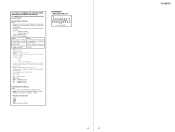
TC-WE475 • Semiconductor Location Ref. Location D306 D307 D318 D451 D601 D701 D702 D703 D704 D705 D706 D707 D708 D709 D710 D711 D712 D713 D714 D715 ...
TC-WE475 • Semiconductor Location Ref. Location D306 D307 D318 D451 D601 D701 D702 D703 D704 D705 D706 D707 D708 D709 D710 D711 D712 D713 D714 D715 ...

Service Manual
Page 16
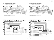
MAIN (2/4) SECTION - • See page 14 for Printed Wiring Board. (Page 22) (Page 15) (Page 17) (Page 17) (Page 17) (Page 18) (Page 18) (Page 19) 16 16 (Page 18) SCHEMATIC DIAGRAM - TC-WE475 6-4.
MAIN (2/4) SECTION - • See page 14 for Printed Wiring Board. (Page 22) (Page 15) (Page 17) (Page 17) (Page 17) (Page 18) (Page 18) (Page 19) 16 16 (Page 18) SCHEMATIC DIAGRAM - TC-WE475 6-4.

Service Manual
Page 17
6-5. MAIN (3/4) SECTION - • See page 13 for Waveforms. • See page 14 for Printed Wiring Board. • See page 26 for IC Pin Functions. (Page 22) (Page 22) (Page 15) (Page 20) TC-WE475 (Page 15) (Page 24) (Page 16) (Page 16) (Page 16) (Page 18) (Page 18) 17 17 (Page 18) SCHEMATIC DIAGRAM -
6-5. MAIN (3/4) SECTION - • See page 13 for Waveforms. • See page 14 for Printed Wiring Board. • See page 26 for IC Pin Functions. (Page 22) (Page 22) (Page 15) (Page 20) TC-WE475 (Page 15) (Page 24) (Page 16) (Page 16) (Page 16) (Page 18) (Page 18) 17 17 (Page 18) SCHEMATIC DIAGRAM -
Service Manual
Page 19
DECK A SECTION - • See page 12 for Circuit Boards Location. DECK B SECTION - • See page 12 for Circuit Boards Location. (Page 14) TO MAIN BOARD 6-9. DECK A SECTION - * PLUNGER SOLENOID is supplied as the Mechanism Deck (TCM-230ASR41B : A-2100-942-A). 6-10. PRINTED WIRING BOARD - DECK B SECTION - TO MAIN BOARD (Page 15) 19 19 TO MAIN BOARD (Page 16) 6-7. SCHEMATIC DIAGRAM - PRINTED WIRING BOARD - SCHEMATIC DIAGRAM - TC-WE475 (Page 14) TO MAIN BOARD * PLUNGER SOLENOID is supplied as the Mechanism Deck (TCM-230ASR41A : A-2100-941-A). 6-8.
DECK A SECTION - • See page 12 for Circuit Boards Location. DECK B SECTION - • See page 12 for Circuit Boards Location. (Page 14) TO MAIN BOARD 6-9. DECK A SECTION - * PLUNGER SOLENOID is supplied as the Mechanism Deck (TCM-230ASR41B : A-2100-942-A). 6-10. PRINTED WIRING BOARD - DECK B SECTION - TO MAIN BOARD (Page 15) 19 19 TO MAIN BOARD (Page 16) 6-7. SCHEMATIC DIAGRAM - PRINTED WIRING BOARD - SCHEMATIC DIAGRAM - TC-WE475 (Page 14) TO MAIN BOARD * PLUNGER SOLENOID is supplied as the Mechanism Deck (TCM-230ASR41A : A-2100-941-A). 6-8.

Service Manual
Page 21
No. Location D904 B-3 D905 B-2 D906 B-2 D907 B-2 D908 B-2 IC901 B-5 IC902 A-2 Q901 A-2 PRINTED WIRING BOARD - 6-12. DISPLAY SECTION - • See page 12 for Circuit Boards Location. (Page 14) TC-WE475 21 21 • Semiconductor Location Ref.
No. Location D904 B-3 D905 B-2 D906 B-2 D907 B-2 D908 B-2 IC901 B-5 IC902 A-2 Q901 A-2 PRINTED WIRING BOARD - 6-12. DISPLAY SECTION - • See page 12 for Circuit Boards Location. (Page 14) TC-WE475 21 21 • Semiconductor Location Ref.

Service Manual
Page 22
PANEL SECTION - (Page 17) (Page 18) (Page 17) TO MAIN BOARD (Page 15) TO MAIN BOARD (Page 16) 22 22 TC-WE475 6-13. SCHEMATIC DIAGRAM -
PANEL SECTION - (Page 17) (Page 18) (Page 17) TO MAIN BOARD (Page 15) TO MAIN BOARD (Page 16) 22 22 TC-WE475 6-13. SCHEMATIC DIAGRAM -

Service Manual
Page 23
PANEL SECTION - • See page 12 for Circuit Boards Location. (Page 14) (Page 14) 1 2 3 4 A B (Page 14) (Page 14) 23 23 TC-WE475 (Page 14) PRINTED WIRING BOARD - 6-14.
PANEL SECTION - • See page 12 for Circuit Boards Location. (Page 14) (Page 14) 1 2 3 4 A B (Page 14) (Page 14) 23 23 TC-WE475 (Page 14) PRINTED WIRING BOARD - 6-14.

Service Manual
Page 25
POWER SECTION - • See page 12 for Circuit Boards Location. 6-16. TC-WE475 (Page 14) 25 25 PRINTED WIRING BOARD -
POWER SECTION - • See page 12 for Circuit Boards Location. 6-16. TC-WE475 (Page 14) 25 25 PRINTED WIRING BOARD -


