
Startup Guide
Page 8
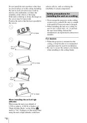
...176; or more When installing the unit at high altitudes When using the unit at an altitude of the lamp. If the unit is mounted on the ceiling, a Sony bracket or recommended equivalent must be sure to use a safety wire, etc., to "On". Position the unit so that the lens ..., such as reducing the reliability of certain components. For dealers • When the projector is tilted up or down, the image on a ceiling, be used for installing the unit on a ceiling • Never mount the projector on the ceiling. Entrust the installation to an experienced contractor or installer.
...176; or more When installing the unit at high altitudes When using the unit at an altitude of the lamp. If the unit is mounted on the ceiling, a Sony bracket or recommended equivalent must be sure to use a safety wire, etc., to "On". Position the unit so that the lens ..., such as reducing the reliability of certain components. For dealers • When the projector is tilted up or down, the image on a ceiling, be used for installing the unit on a ceiling • Never mount the projector on the ceiling. Entrust the installation to an experienced contractor or installer.

Operating Instructions
Page 69
The distance between the front of the lens and the front of the cabinet Unit: mm (inches) 36.8 (1 7/16) Front of the lens Front of the cabinet Attaching the PSS-H10 projector suspension support Front view 150 (5 29/32) 75 (2 15/16) 8 (5/16) Ceiling Center of the supporting pole 175 (6 7/8) Unit: mm (inches) The bottom surface of the mount bracket 118 (4 21/32) Center of the lens 69
The distance between the front of the lens and the front of the cabinet Unit: mm (inches) 36.8 (1 7/16) Front of the lens Front of the cabinet Attaching the PSS-H10 projector suspension support Front view 150 (5 29/32) 75 (2 15/16) 8 (5/16) Ceiling Center of the supporting pole 175 (6 7/8) Unit: mm (inches) The bottom surface of the mount bracket 118 (4 21/32) Center of the lens 69
Operating Instructions
Page 70
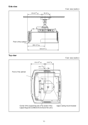
Side view 213.4 (8 13/32) 130 (5 1/8) Unit: mm (inches) Front of the cabinet Top view Front of the cabinet 258.4 (10 3/16) 463.6 (18 1/4) 213.4 (8 13/32) 130 (5 1/8) 45 (1 25/32) Unit: mm (inches) Center of the supporting pole (The center of the supporting pole is different from that of the unit.) Upper ceiling mount bracket 70
Side view 213.4 (8 13/32) 130 (5 1/8) Unit: mm (inches) Front of the cabinet Top view Front of the cabinet 258.4 (10 3/16) 463.6 (18 1/4) 213.4 (8 13/32) 130 (5 1/8) 45 (1 25/32) Unit: mm (inches) Center of the supporting pole (The center of the supporting pole is different from that of the unit.) Upper ceiling mount bracket 70
Operating Instructions
Page 71
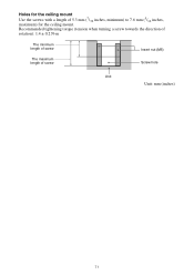
Recommended tightening torque (tension when turning a screw towards the direction of rotation): 1.4 ± 0.2 N-m The minimum length of screw The maximum length of 5.3 mm (7/32 inches, minimum) to 7.6 mm (5/16 inches, maximum) for the ceiling mount. Holes for the ceiling mount Use the screws with a length of screw Insert nut (M5) Screw hole Unit Unit: mm (inches) 71
Recommended tightening torque (tension when turning a screw towards the direction of rotation): 1.4 ± 0.2 N-m The minimum length of screw The maximum length of 5.3 mm (7/32 inches, minimum) to 7.6 mm (5/16 inches, maximum) for the ceiling mount. Holes for the ceiling mount Use the screws with a length of screw Insert nut (M5) Screw hole Unit Unit: mm (inches) 71


